
Switchgear Busbar Manufacturing Reference
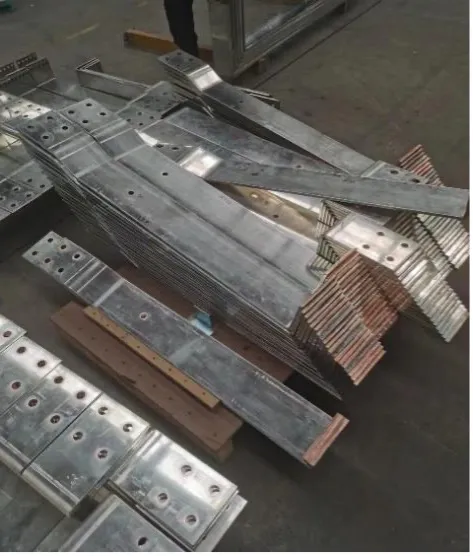
Switchgear busbar manufacturing converts an approved electrical and mechanical design into repeatable conductors. The fabrication team does not create compliance by choosing a machine; it preserves the design intent through material control, datums, punching, cutting, bending, surface preparation, identification and inspection.
This reference connects drawing requirements to shop-floor controls. Always use the current project specification and applicable standards for electrical clearances, temperature-rise verification, short-circuit withstand, dielectric performance and safety.
1. Start With the Verified Assembly Design
Before releasing busbars to production, the controlled drawing or digital model should identify:
- material grade, temper, plating or coating condition;
- width, thickness and finished length;
- reference datums and bend sequence;
- hole and slot sizes, positions and edge distances;
- bend angle, orientation and inside radius;
- interfaces with insulators, terminals, links and enclosures;
- burr, surface, flatness and cosmetic requirements;
- part number, revision and phase/position identification;
- inspection method and acceptance limits.
Do not let an operator infer missing requirements from a previous project. Resolve them through the engineering change process.
2. Control Incoming Material
Copper and aluminum respond differently to cutting, punching, bending, plating and joint preparation. Even within one material family, temper and thickness affect springback and required force.
At receiving, connect each batch to:
- purchase specification and supplier certificate;
- material grade and temper;
- measured width and thickness;
- surface condition and protective packaging;
- heat, lot or internal traceability number;
- approved substitution record, if any.
Store long bars with support that prevents permanent set. Separate bare, plated and coated material to protect surfaces and avoid mix-ups.
3. Translate Drawings Into a Stable Datum Strategy
Cumulative error often comes from changing datums between operations. Define where the part is referenced for punching, cutting, bending and final inspection.
| Feature | Datum decision |
|---|---|
| Hole pattern | edge, end or established feature used as zero |
| Cut length | raw-stock allowance and finished reference end |
| Bend position | tangent, centerline or tooling reference |
| Bend direction | face-up/down and part orientation |
| Multiple bends | sequence and which feature controls the next setup |
| Final fit | interface points checked in the assembly gauge or enclosure |
The program name should include the part number and revision. Lock obsolete revisions out of production, and retain an approved setup sheet with the tool and material condition.
4. Punching and Slotting Controls
For each feature, confirm tool size, clearance, orientation and remaining material around edges and adjacent holes. Inspect more than the nominal center position:
- feature size and form;
- pitch and position from the defined datum;
- edge distance;
- burr direction and height requirement;
- deformation, rollover or tearing;
- tool wear and slug evacuation;
- relationship to a future bend line.
Run a first-off part after program, tool, material batch or setup changes. Retain the actual measurements rather than only a pass mark.
5. Shearing and Cut-Length Controls
Cut quality affects downstream location and joint fit. Define:
- finished length and measurement temperature, if critical;
- permitted squareness or angular deviation;
- edge condition and deburring method;
- which cut end becomes the production datum;
- support method for long or heavy sections;
- segregation of reusable offcuts by material and lot.
Material utilization should be calculated from the plant’s real part list, stock lengths and remnant policy. Validate any nesting claim by comparing identical orders and rules.
6. Bending Controls
Bending changes angle, position, material surface and sometimes the relationship between previously punched features. A controlled process includes:
- material grade, temper and thickness;
- punch/die or bending tool identification;
- inside radius and tool orientation;
- bend sequence and collision check;
- springback trial and approved correction;
- angle and bend-position measurement method;
- inspection at operating condition when production heat matters;
- protection of plated or finished surfaces.
Do not transfer a correction value blindly between material lots. Produce a first-off sample and update only the controlled recipe.
7. Deburring, Surface Treatment and Joints
Fabrication must preserve the joint design. Remove sharp edges and loose burrs without altering required contact geometry. Before plating, coating or insulation, define masked areas and the treatment applied to electrical contact surfaces.
For assembled joints, the design authority should specify surface preparation, hardware, washer arrangement, tightening method and inspection record. Aluminum requires particular control of oxide and surface preparation; use the approved engineering process and joint-system instructions.
8. Build an Inspection Plan Around Risk
Not every dimension needs the same frequency. Classify features by their consequence and process stability.
| Inspection stage | Typical checks |
|---|---|
| Incoming | material identity, thickness, width and surface condition |
| First-off | all drawing-critical features and orientation |
| In-process | high-risk positions, tool condition and recipe control |
| After bending | angle, bend position, twist and interface dimensions |
| Final | part/revision ID, finish, complete geometry and quantity |
| Assembly fit | supports, terminals, phase spacing and enclosure interface |
Record the instrument, operator, date, part/lot ID and measured value for critical features. A traceable value is more useful than a photo of a caliper.
9. Select Equipment From the Production Flow
Three-station busbar processing machine
Best considered when punching, shearing and bending must remain available to separate operators in a compact mixed-production area. Evaluate station interaction, material handling, tool change and actual part routing. See the DH303-8P 3-in-1 busbar machine.
CNC punching and shearing machine
Best considered when repeated hole/slot patterns, program reuse and cut workflow dominate the bottleneck. Verify position results and import workflow on buyer drawings. See the DHCNC-BP-60 CNC punching and shearing machine.
Dedicated CNC busbar bender
Best considered when bend control, multiple orientations and repeatable recipes justify a dedicated station. Validate angle and springback workflow across the actual material range. See the DHAC-BB-H CNC busbar bending machine.
For a full architecture decision, use the CNC busbar machine selection guide.
10. Calculate Capacity With Routing Data
Avoid multiplying a supplier’s fastest single operation by shift minutes. Model the complete routing:
- classify representative part families;
- count punches, cuts, bends, setups and handling moves;
- measure programming, loading, unloading and inspection time;
- include changeovers, maintenance and realistic availability;
- identify whether the bottleneck moves after automation;
- test the assumptions during FAT or a time study.
For mixed production, a flexible parallel workstation may outperform a faster isolated cycle. For repeated families, program reuse and automated positioning may dominate. The correct answer depends on the part mix.
11. FAT for a Switchgear Busbar Process
Select sample parts that represent risk:
- longest and shortest stock;
- minimum and maximum thickness;
- dense patterns and holes near bend lines;
- multiple bend orientations;
- plated or protected surfaces where relevant;
- parts that interface with fixed terminals or supports.
Require raw measurement results, program revisions, tool IDs and deviations. The FAT should demonstrate the workflow the factory will actually use, including setup, inspection and program recovery.
12. Production Record to Retain
The finished record should connect:
material lot → drawing revision → program revision → tooling/setup → operator/machine → measurements → treatment lot → assembly position
This chain supports troubleshooting and prevents a later nonconformance from becoming an unbounded search. It also gives the factory the data needed to improve tooling, maintenance and scheduling without inventing generic savings percentages.
Frequently Asked Questions (FAQs)
Does using a CNC busbar machine make a switchgear assembly compliant?
No. CNC equipment can improve control and traceability of fabricated dimensions, but assembly compliance depends on the complete verified design, materials, joints, supports, clearances, protective devices and production controls. Acceptance criteria must come from the applicable project documents and current standards.
Which busbar dimensions should be controlled in production?
Control the drawing-critical datums: hole and slot locations, edge distances, cut length, bend position, bend orientation, inside radius, angle, twist, flatness and interfaces with supports or terminals. The drawing should state how each feature is measured.
How should a factory choose between a 3-in-1 machine and dedicated CNC machines?
A 3-in-1 workstation suits mixed work and parallel operators; dedicated punching/shearing and bending machines suit separated flows, repeatable programs and higher utilization. Base the choice on routing, batch mix, bottlenecks, handling and FAT results rather than a generic output claim.
DHCNC-BP-60 CNC Punching & Shearing Workstation
Discover details, parameters, standard dies packages, and factory quotes.