
Busbar Fabrication Process: From Copper Stock to Finished-Part Quality Control
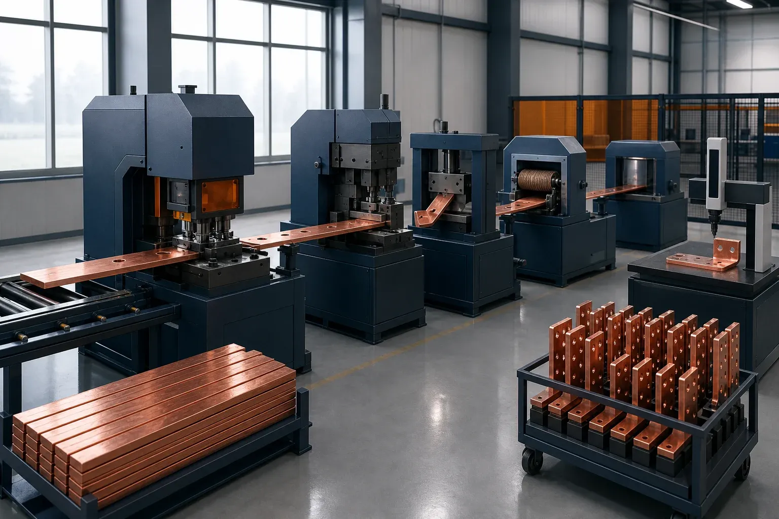
Busbar fabrication is not a fixed list of machines. It is a controlled conversion from an electrical and mechanical design into a finished conductor that fits the assembly, carries the specified duty, and can be traced to the released drawing and material.
A stable process catches risk at the earliest economical point. Material errors are found at receipt, datum and hole errors before bending, bend errors before finish, and surface or insulation defects before packing. Final inspection then confirms the completed part instead of discovering problems that have already consumed every downstream operation.
ISO 9001:2015 is the published quality-management standard referenced here; its process and documented-information framework can support this control plan, but the organization must still define its own product-specific route and acceptance evidence. ISO’s catalogue lists the replacement edition as under publication, so revise QMS references only after confirming the issued edition and transition requirements.
Convert the Drawing Into a Controlled Process Plan
Review the drawing before releasing material. Identify the material grade and condition, thickness and width, final datums, current-carrying and contact surfaces, holes and slots, bend types, finish, insulation, markings, and critical-to-fit characteristics. Resolve ambiguous dimensions with engineering rather than at the machine.
The busbar drawing tolerance guide shows how to translate assembly interfaces into functional datums, hole-position controls, measurable bend results, and a first-article plan without tightening every dimension unnecessarily.
The process plan should state:
- drawing and revision;
- material and lot-control requirement;
- operation sequence and work centers;
- program, tooling, and fixture identification;
- first-piece and in-process checks;
- final acceptance source;
- permitted rework and approval authority;
- packaging and handling for functional surfaces.
The switchgear busbar manufacturing reference adds assembly context, while this article focuses on the production route itself.
Verify Stock Before Cutting
Check that the received conductor matches the purchase specification. Review the material certificate when required and verify section dimensions, flatness, surface condition, and lot identification. Separate suspect material before it enters nesting.
For copper-grade decisions within that specification, use the C110, C101, and C102 material guide. It separates alloy identity from temper and joining requirements, so a material substitution does not enter production on a grade name alone.
Copper and aluminum cannot be exchanged by maintaining the same external dimensions. Conductivity, density, mechanical behavior, surface oxide, joint preparation, and forming response differ. Use the copper-versus-aluminum machining guide when the design permits either material.
Store and handle bars so they do not acquire deep scratches, edge damage, contamination, or uncontrolled bends. Contact surfaces and parts scheduled for plating deserve dedicated protection.
Nest and Prepare Blanks for the Downstream Route
Nesting should preserve stable datums and account for clamp margins, kerf or shear allowance, remnant handling, bend orientation, grain or rolling direction where the process requires it, and part identification. Material utilization is important, but a layout that saves copper while creating unstable clamping or the wrong forming orientation is not efficient.
Use a controlled remnant policy: mark material identity, remaining dimensions, and permissible reuse. The 3D nesting and copper-waste resource explains yield optimization without treating a headline saving percentage as guaranteed for every part mix.
After shearing, verify blank length, width, squareness where critical, deformation, and edge condition. A sheared edge that will become a dielectric boundary or contact-adjacent surface may need more stringent control than a nonfunctional outside edge.
Punch Holes Without Losing Datum Control
Program holes and slots from the drawing datums. Confirm the correct tool, die clearance, orientation, material thickness, and program revision before the first stroke. Inspect the first piece for hole size, pitch, edge distance, burr, distortion, and relationship to later bends.
Tool wear can change edge quality before it creates an obvious dimensional failure. Track visual condition, burr trend, maintenance, and tool life according to the actual material. Do not wait for a damaged batch to establish a replacement interval.
A DHCNC-BP-60 punching and shearing workstation is one equipment route for repeat parts. Its formal specifications should be checked against the material and trial drawing; the project tolerance remains the released drawing’s value.
Bend in a Sequence That Preserves Access and Geometry
Bend sequence determines whether the tool can reach later features and whether completed bends collide with the machine, fixture, or part itself. Simulate or review the sequence before production, particularly for offsets, U bends, edge bends, and three-dimensional conductors.
Control material, tool radius, bend direction, stroke or angle setting, and first-piece result. Springback compensation belongs to a part-and-material process record, not a generic operator memory. Measure the final formed datums after unloading.
For thick or twisted transformer parts, use the dedicated transformer busbar fabrication guide. For equipment architecture, compare a multi-function machine with a dedicated servo-hydraulic bender using the real production mix.
Deburr, Clean, Finish, and Mask Functional Surfaces
Deburring should remove sharp edges and loose material without rounding a datum, thinning a terminal, embedding abrasive particles, or scratching a contact face. Clean the part with a method compatible with the next finish and the project specification.
Plating and insulation are different operations with different purposes. The surface-treatment guide addresses contact finish and corrosion strategy. The busbar-insulation guide addresses dielectric coverings, barriers, and process sequence.
Masking boundaries should be dimensioned and repeatable. After outside processing, verify that the correct part and revision returned, functional areas remained protected, and the finish did not hide a burr, crack, or dimensional nonconformance.
Inspect Where Failure Is Cheapest to Detect
| Stage | Control purpose | Example records |
|---|---|---|
| Incoming | prevent wrong or damaged material entering production | certificate, section measurement, lot tag |
| First piece | validate program, tool, route, and measurement | dimensional report and approval |
| In process | detect drift before the batch is complete | periodic CTQ results, tool checks |
| Post-form | confirm final datums before finish | fixture, angle, plane, envelope results |
| Post-finish | verify contact, coating, insulation, and identity | visual and specified process tests |
| Final release | confirm complete drawing and documentation | finished-part checklist and disposition |
Sampling and measurement methods should be risk-based and agreed for the project. A single first piece may validate setup but cannot reveal every wear or material-lot effect. Conversely, measuring every noncritical feature can consume resources without reducing meaningful risk.
The NIST policy on metrological traceability is useful here: traceability requires a documented calibration chain, while traceability alone does not prove that a measurement is fit for its intended tolerance.
The finished copper busbar inspection checklist provides a field structure for final acceptance.
Close the Loop With Traceability and Nonconformance Data
Link the finished part to its drawing, material lot, program, tools, first-piece approval, in-process results, outside finish, final inspection, and packaging. Record authorized rework and concessions. If a recurrent defect appears, analyze it by part family, operation, material, tool, and shift rather than treating each event as isolated.
The existing supplier traceability and QC protocol addresses the broader quality system. At process level, the goal is simple: a released part should be reproducible, and any change that can affect fit or function should be visible to engineering before shipment.
Match Equipment Architecture to the Bottleneck
Separate machines can provide flexibility and parallel capacity. A multi-function unit can reduce handling and floor space for a suitable mixed part set. A dedicated CNC line can improve repeat work with controlled programs and material handling. None is automatically best.
Use actual part-family volume, setup frequency, routes, maintenance, operator availability, WIP, inspection, and demonstrated yield. Run representative parts from the thinnest and thickest materials and include the hardest hole-to-bend relationship. That evidence turns an equipment comparison into a production decision.
Frequently Asked Questions (FAQs)
What are the main steps in copper busbar fabrication?
A typical route is drawing and process review, material verification, nesting and blank preparation, punching or machining, shearing, bending, deburring and cleaning, plating or insulation where required, final inspection, marking, packaging, and traceability release. The sequence changes with the part.
Should busbar holes be punched before or after bending?
Punching before bending is efficient when forming will not distort the hole or move it outside the final tolerance. Critical terminal features may need post-form machining or compensation. Decide from the final datums, volume, geometry, and a representative trial.
How are burrs controlled after punching and shearing?
Use suitable, maintained tooling and a controlled clearance first, then apply a defined deburring method. Inspect both sides and edges, protect contact faces, and verify that deburring has not changed a critical dimension or left abrasive contamination.
Which busbar dimensions should be checked during production?
Check the characteristics that control fit and function: material section, blank datums, hole and slot geometry, bend location and angle, final terminal planes, overall envelope, contact areas, finish or insulation cutbacks, and any project-defined critical features.
How do manufacturers choose between separate and multi-function busbar machines?
Compare the actual part-family routes, material range, setup frequency, bottleneck utilization, required flexibility, maintenance, operator coverage, floor space, and finished-part throughput. A representative trial is more reliable than comparing nominal cycle rates.
DHCNC-BP-60 CNC Punching & Shearing Workstation
Discover details, parameters, standard dies packages, and factory quotes.