
Busbar Short-Circuit Calculations: Icw, Ipk, and Support Spacing
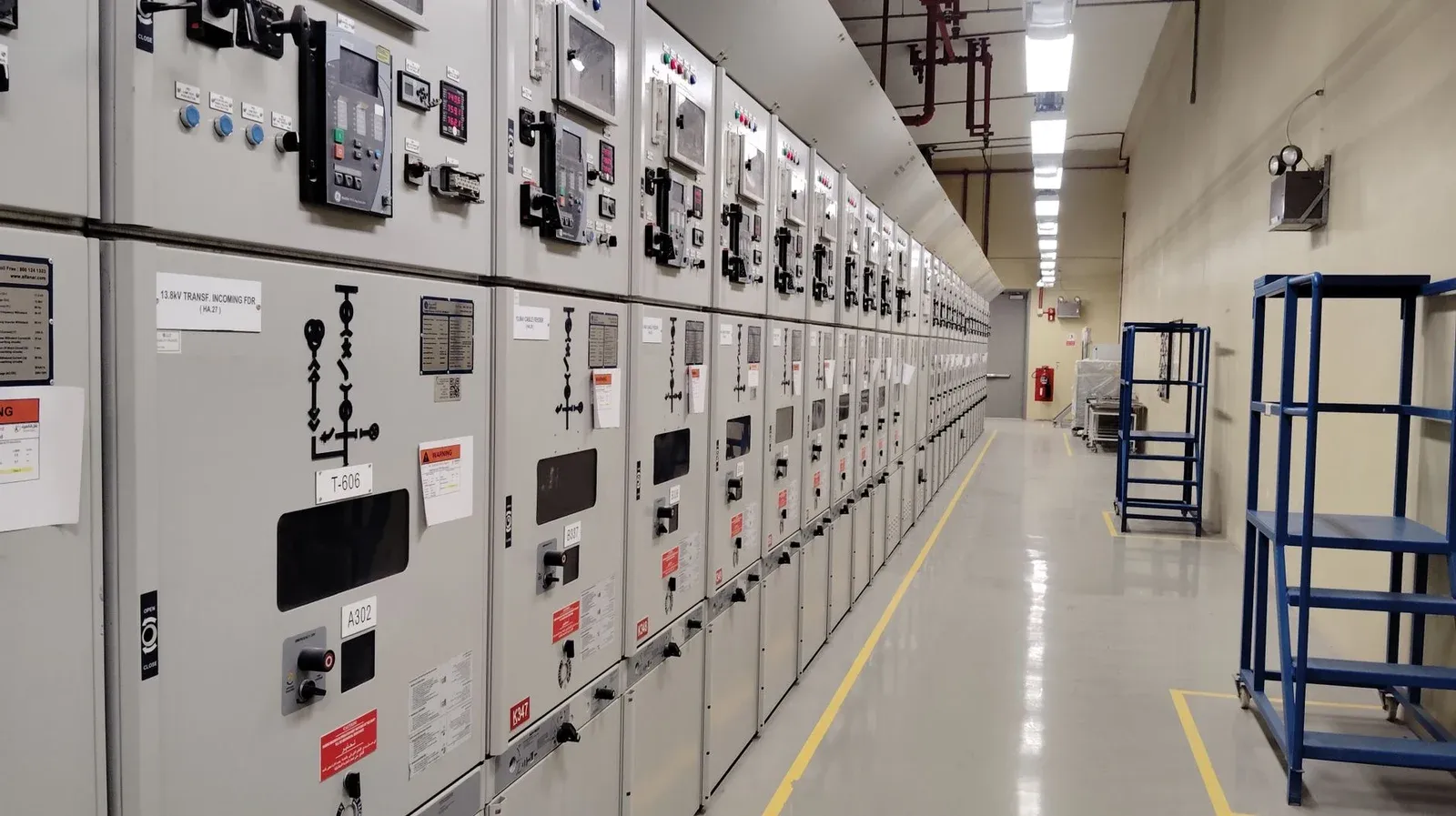
“50 kA” is not a complete busbar specification. It might refer to a prospective fault level, a short-time withstand rating with a stated duration, a peak current, or the performance of an assembly used with a particular protective device. Those meanings cannot be exchanged without changing the engineering question.
A useful short-circuit calculation separates thermal exposure from mechanical loading, then checks both against the complete assembly. Copper cross-section matters, but so do support spacing, orientation, joints, and the protection that determines what the assembly actually experiences.
The following calculations explain the distinctions. They are screening examples, not a substitute for the applicable verification method or an electrical engineer’s fault study.
Start With the Fault Study, Not the Copper Cross-Section
Obtain the prospective short-circuit duty at the location being designed. A transformer-terminal result may not be the same as the duty at a downstream panel. Include the relevant operating configurations, parallel sources, and contributions identified by the system study.
Next identify the protective device, its settings, and its behavior at that prospective fault level. If a design relies on current limitation, use the manufacturer’s applicable let-through information and the verified coordination conditions. A breaker’s headline interrupting rating is not automatically the current experienced by every conductor during a fault.
The fabrication drawing should not be released while these inputs remain undefined. Otherwise, the workshop may accurately reproduce a geometry that has never been assessed for the intended electrical duty.
Protection selection belongs alongside the busbar protection and coordination discussion. The focus here is the conductor-and-support assembly that must withstand the resulting load.
Icw and Ipk Answer Different Questions
Keep the rating symbols and their conditions together in the technical file.
| Quantity | What it describes | Information that must accompany it |
|---|---|---|
| Continuous current rating | Normal operating current under declared conditions | Temperature, enclosure, arrangement, and installation conditions |
| Icw | Rated short-time withstand current, expressed as RMS | The stated duration and assembly configuration |
| Ipk | Rated peak withstand current | The verified mechanical configuration and applicable peak duty |
| Conditional short-circuit rating | Performance associated with specified protection | The exact protective device and coordination conditions |
ABB’s System pro E power assembly guidelines relate busbar support selection and spacing to conductor configuration and short-circuit performance. That is the important principle: the rating belongs to an arrangement, not to an isolated copper bar.
A cabinet photograph cannot establish any of these ratings. Nor can a material certificate establish the short-circuit capability of the assembled switchboard.
What an I²t Comparison Can and Cannot Prove
For a simplified constant-RMS comparison, thermal exposure is often expressed using current squared multiplied by time. Consider two assumed duties:
50² × 1 = 2,500 kA²s
25² × 4 = 2,500 kA²s
The arithmetic is equal. It does not mean an assembly rated at 50 kA for one second is automatically approved for 25 kA for four seconds. The allowed assessment method, conductor temperature limits, component behavior, and time range still matter.
For a time-varying current, the relevant expression is an integral of current squared over time, not simply a convenient current multiplied by a guessed clearing time. Current-limiting devices further reinforce the need for the applicable manufacturer data.
Do not use an I²t comparison to bypass a support check. Mechanical forces respond to instantaneous current, and their interaction with the structure is different from a thermal energy comparison. The initial asymmetrical peak can matter even when the duration is short.
Use Force Calculations as Screening, Not Certification
For two idealized long, parallel conductors with equal instantaneous current magnitude, a basic force-per-length expression is:
q = 2 × 10⁻⁷ × i² / d
Use amperes for i and meters for conductor separation d; the result is newtons per meter. This idealized relation helps explain the sensitivity to current and spacing. It omits the finite geometry, phase relationships, multiple bars, and dynamic response of a real assembly.
For an assumed instantaneous current of 100,000 A and separation of 0.10 m:
q = 2 × 10⁻⁷ × 100,000² / 0.10 = 20,000 N/m
Using a smaller RMS value in place of the intended instantaneous current would answer a different question. Doubling current in this model multiplies force by four; halving separation doubles it.
The force result alone does not determine a safe support span. Bending stress, deflection, conductor orientation, support strength, fixity, and dynamic effects must also be evaluated. The mechanical treatment in Copper for Busbars discusses these dependencies. A simple two-conductor example should not be represented as a three-phase assembly certification calculation.
Match Support Spacing to the Reference Assembly
Where an assembly system provides verified configurations, identify the exact reference: conductor size and count, phase spacing, bar orientation, support type, maximum span, mounting structure, and connections. Confirm the conditions under which that reference can be used.
Small-looking changes can matter. Turning a rectangular bar changes its bending stiffness in the load direction. Adding a bar may change current sharing and the support arrangement. Moving a bracket can create a longer unsupported span at a terminal even when the rest of the run is unchanged.
Do not extract one spacing value from a supplier drawing and apply it to every switchboard. The dimensions are meaningful only with the associated configuration and rating. If the design departs from that arrangement, the assembly designer must select the permitted verification route and document the result.
The broader IEC 61439 fabrication guide provides the compliance context for low-voltage assemblies. It does not turn a workshop inspection into design verification.
Freeze the Evidence Before Releasing Fabrication
A short-circuit release package should connect the approved electrical duty to dimensions that production can inspect. Include the reference design or assessment, controlled drawings, support part numbers, hole locations, fastening instructions, and any restrictions on substitutions.
During manufacture, verify those features against the drawing. Use the finished-busbar inspection controls for geometry and identity, and the assembly inspection plan for supports and mounting. Record departures before the equipment is closed up.
When discussing a switchgear manufacturing project, define who owns the system fault study, assembly verification, component manufacture, and final release. A precise punching machine can reproduce the specified hole pattern; it cannot decide whether that pattern provides adequate short-circuit support.
The final decision should be traceable: this duty, with this protection, is supported by this evidence for this exact assembly. That is more useful than an unexplained kA number on a quotation.
Frequently Asked Questions (FAQs)
Does increasing copper thickness prove short-circuit withstand?
No. Thickness affects some thermal and mechanical properties, but the complete configuration also includes bar orientation, phase spacing, supports, joints, restraints, and protection. Verify the changed assembly rather than assuming a larger bar preserves its rating.
Can I always calculate Ipk by multiplying Icw by the square root of two?
No. That relationship describes the peak of a symmetrical sinusoid. Fault asymmetry and the applicable rating or calculation method must be considered when establishing the relevant peak duty.
Can a 1-second rating be converted to any longer duration using I squared t?
Not without confirming the permitted method and its limits. Equal mathematical I squared t does not, by itself, establish equivalent assembly performance, temperature limits, mechanical behavior, or protection coordination.
Should a changed support hole pattern be reviewed?
Yes. Moving mounting holes or changing support brackets can alter span, load path, and stiffness. The responsible assembly designer should confirm that the altered arrangement remains covered by its verification.