
Transformer Busbar Fabrication: Thick Copper, Twist Bends, and Terminal Accuracy
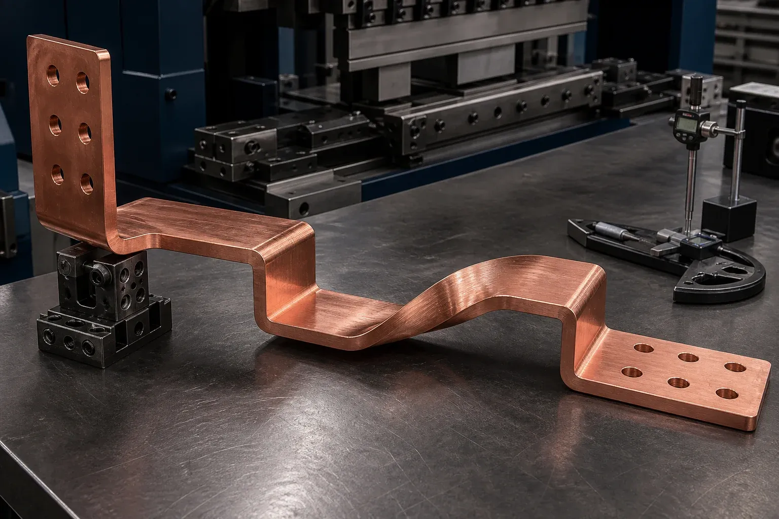
Transformer busbar fabrication is a datum problem disguised as a bending problem. A bar can have the correct individual angles and still fail to assemble because the final terminal planes, hole pattern, and enclosure clearance do not relate to the same reference system.
This is especially important with thick copper, edge bends, offsets, and twists. Each operation changes the geometry available to the next one. A production route must therefore be designed from the two connected transformer interfaces back toward the flat blank.
Start From Transformer Terminals and Assembly Datums
Define what the conductor connects: winding lead, bushing, tap changer, neutral, ground point, switch, or busduct transition. Record the mating surfaces, allowable assembly sequence, tool access, insulation space, and any motion caused by transport or thermal expansion.
IEC 60076-1 provides the general standard framework for power transformers, but it does not replace the manufacturer’s controlled terminal geometry or part drawing. Fabrication acceptance must therefore follow the transformer design, purchase specification, and applicable project standards as a coordinated set.
Use final-part datums that production and quality can reproduce. Examples include one terminal plane, a primary hole pair, a centerline, and a second controlled plane. Avoid a chain of dimensions that accumulates uncertainty through every bend.
The transformer and busduct application page describes the production context. The released drawing remains the source for current, material, insulation, clearance, and acceptance requirements.
Choose Copper Section and Condition With the Route in Mind
Electrical design establishes conductor area and material. Manufacturing then needs the exact grade, temper or condition, thickness, width, grain or rolling direction where relevant, surface finish, and permissible edge condition. Nominal “copper” is not enough for repeatable forming.
Thicker and wider bars need more force and support, but force alone does not decide manufacturability. Tight radii can produce surface strain and cross-section distortion. Edge bending can encourage lateral instability. A twist introduces distributed shear and may alter terminal flatness.
Use the busbar bending-force and tonnage calculation as a screening tool, then confirm tooling and part quality with the actual material. A calculation does not predict every local deformation in a complex conductor.
Separate Flat Bends, Edge Bends, Offsets, and Twists
| Geometry | Primary challenge | Tooling concern | Final inspection |
|---|---|---|---|
| Flat bend | springback and bend location | radius, support, surface marking | angle, location, terminal plane |
| Edge bend | lateral instability and width distortion | guided support and suitable die geometry | edge curvature, width, flatness |
| Offset or Z bend | interaction between adjacent bends | sequence, access, minimum spacing | offset height, parallelism, fit |
| Twist | distributed deformation and terminal rotation | controlled grip length and torsion path | rotation, straightness, terminal flatness |
| U bend | tool access and inner clearance | punch/die envelope and extraction | inside width, leg parallelism, height |
Do not describe a sharp local buckle as a controlled twist. A sound twist distributes rotation over a designed length and preserves the terminal zones. The acceptable surface and dimensional condition comes from the engineering drawing and qualified trial.
Control Springback and Local Distortion
Springback varies with material condition, section, radius, tool friction, forming direction, temperature, and previous work. A stored compensation value is useful only when those inputs remain controlled.
A practical method is to:
- verify material and lot;
- form a representative first piece with the approved tool;
- measure the final part after unloading and stabilization;
- adjust the controlled stroke or angle setting;
- repeat until the final datums meet the drawing;
- record the setting with the material and program revision;
- monitor drift and tool wear during the batch.
This is more defensible than promising “zero springback.” The springback-control resource should be read as process guidance, while acceptance remains measurement of the released part.
Reference Hole Patterns to the Final Geometry
Pre-punching holes is efficient for many parts, provided bending does not deform the terminal or move the features outside tolerance. Protect the hole area from direct forming pressure and leave enough edge distance according to the design.
For critical interfaces, compare three strategies: punch all features in the flat; punch rough or noncritical features before forming and finish critical holes afterward; or use a final fixture/CMM result to compensate the flat program. The correct choice depends on volume, tolerance, geometry, and available process capability.
A go/no-go assembly fixture representing the mating transformer terminals can catch a relationship that individual hole and angle checks miss.
Build the Route Around the Hardest Operation
Map the complete sequence—cut, punch, flat bend, edge bend, twist, deburr, clean, finish, mark, and inspect—then identify the operation with the least process margin. That operation often determines tooling, batch order, and first-piece strategy.
A DH303-8P multi-function processing configuration can support mixed punching, shearing, and forming work. A dedicated DHAC-BB-H bending station may suit controlled bend families. Neither should be selected from the article alone: the buyer should trial the hardest real part, confirm the formal product specification, and separate standard dies from custom tooling.
Surface treatment timing also matters. Bending after plating can damage the finish, while plating a complex final shape can complicate racking, masking, and thickness uniformity. Decide the route with the finish supplier before production release.
Inspect Fit Before the Part Reaches Final Assembly
Final inspection should confirm:
- material and drawing revision;
- terminal hole size, location, and edge condition;
- bend locations, angles, offsets, and twist rotation;
- terminal-plane flatness and parallelism as specified;
- overall envelope and enclosure clearances;
- contact-surface finish and protection;
- burrs, cracks, severe marks, or local distortion;
- insulation or plating cutbacks where applicable;
- part identity, orientation, and packaging.
Measure the part in a stable, repeatable condition. If the conductor is compliant enough to sag, define support points. If a custom fixture is used, control and periodically verify the fixture.
Put the Real Part Into the Equipment RFQ
Provide both 2D and 3D data, the specified material and condition, annual and batch quantities, the critical-to-fit datums, finish, current process, and inspection plan. Mark which dimensions have caused assembly problems before.
Ask the equipment or fabrication supplier to return a trial plan showing the route, tools, measuring method, sample count, and any features outside its standard capability. That response is more valuable than a general statement that the machine can perform flat, edge, U, and twist bends.
Frequently Asked Questions (FAQs)
What is a busbar used for inside a transformer?
A busbar or lead conductor provides a high-current connection between transformer windings, bushings, tap equipment, neutral or ground points, and external terminals. Its geometry, insulation, joints, and support depend on the transformer design.
What is the difference between flat, edge, and twist busbar bends?
A flat bend forms the bar in the direction of its thickness, an edge bend forms it in the direction of its width, and a twist rotates the terminal plane along the bar length. Each mode needs different force, support, tooling, and inspection.
Should terminal holes be punched before or after bending?
Punching before bending is efficient when the forming operation will not distort the features and the program references the final geometry correctly. Post-form machining may be justified for a critical terminal interface. The choice should be validated on the actual material and route.
How is springback controlled in thick copper busbars?
Control the material grade and condition, tool radius, forming direction, stroke or angle compensation, and first-piece measurement. Store approved settings by part and material lot where appropriate, then verify the final terminal datums rather than only the commanded angle.
What is needed for a transformer busbar machine trial?
Provide the controlled material, 2D and 3D drawing, critical final datums, finish, required operations, representative quantities, inspection method, and acceptance criteria. Include the most difficult bend and terminal relationship, not only a straight sample.
DH303-8P 3-in-1 CNC Busbar Processing Machine
Discover details, parameters, standard dies packages, and factory quotes.