
Busbar Temperature-Rise Testing for IEC 61439 Assemblies
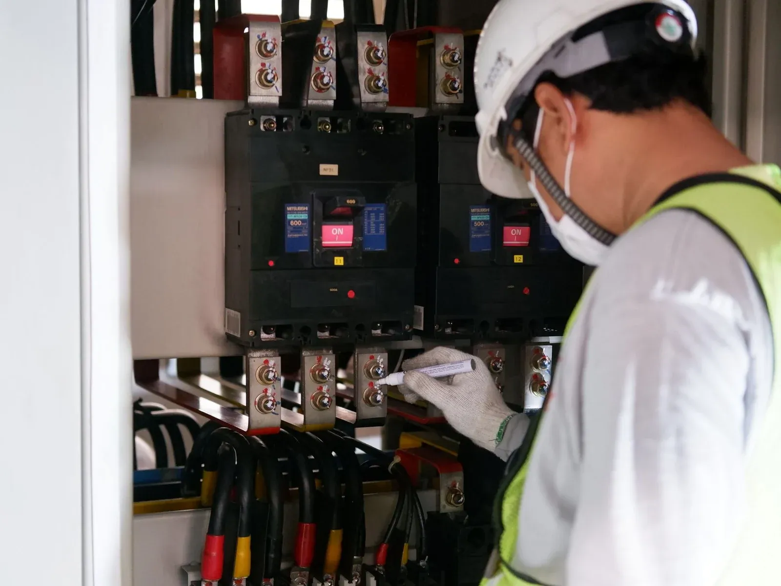
A busbar temperature-rise test is a verification of a defined low-voltage assembly, not a certificate for a copper cross-section in isolation. The same bar can run at different temperatures when joint design, enclosure ventilation, adjacent devices, conductor spacing, loading, or ambient conditions change.
That is why a useful test starts before the current source is connected. Engineering must freeze the tested configuration, define the loading and ambient method, map the sensors, select the applicable acceptance limits, and agree how thermal stability will be demonstrated. Without those controls, a passing number is difficult to reproduce and a failing number is difficult to diagnose.
A Temperature-Rise Test Verifies the Assembly, Not Copper Alone
IEC 61439-1:2020 establishes the general rules for low-voltage switchgear and controlgear assemblies. The relevant design-verification framework recognizes that current-carrying performance depends on the assembly as constructed. An ABB application paper on IEC 61439 explains the verification context and the available routes subject to their conditions and limitations.
A test result therefore belongs to a controlled design envelope. It includes:
- busbar material, section, route, spacing, joints, plating, and supports;
- incoming and outgoing conductors and the way they are connected;
- protective and switching devices installed in the current path;
- enclosure size, partitions, covers, vents, and orientation;
- test current, loading of circuits, ambient reference, and duration;
- the temperature limits assigned to the relevant components and interfaces.
Do not label a test simply “100 × 10 mm copper busbar at 2,000 A.” That description omits the thermal system that produced the result.
Freeze the Test Configuration Before Applying Current
Issue a test drawing or configuration record with the same discipline as a production drawing. Identify assembly model, revision, rated-current arrangement, busbar and joint details, installed devices, terminal conductors, covers, ventilation, and any deviations from the production design. Photograph the completed setup after it is closed in the intended test condition.
Define which circuits are loaded and at what current. A diversity or simultaneous-loading assumption must come from the applicable design and verification method, not from what makes the laboratory setup convenient. Schneider Electric’s explanation of rated current under IEC 61439 is a useful reminder that assembly ratings and operating conditions must be stated together.
Record the current-measurement method, source waveform where relevant, conductor arrangement outside the enclosure, and ambient reference locations. External test leads can carry heat into or away from terminals, so their size, length, routing, and connection should be controlled.
Place Sensors Where the Thermal Path Can Fail
The sensor map should follow the current and heat paths. Typical candidates include incoming terminals, outgoing terminals, bolted joints, flexible links, representative points on long conductor runs, device terminals, and ambient references. The final map depends on the design and applicable limits; it is not a fixed quantity of thermocouples per panel.
Use unique channel IDs and show each location on a drawing or annotated photograph. Record the sensor type, attachment method, wire routing, instrument, and calibration status. A poorly attached sensor can read the surrounding air, while a large metal clip or misplaced adhesive can alter heat transfer.
Avoid placing every sensor on the most accessible face. A joint hidden behind a barrier may be more important than a straight bar in open air. Phase arrangement can also create unequal heating, so equivalent locations on different phases help distinguish a local connection issue from the general assembly trend.
Define Stability and Acceptance Before the Run
The procedure must say how often current, ambient, and channel temperatures are logged and what condition constitutes thermal stability. Use the criterion required by the applicable standard edition, laboratory procedure, and project specification. Do not decide after viewing the curve that a favorable plateau “looks stable.”
Likewise, there is no safe universal statement that every bare copper busbar may rise by one fixed number. Acceptance can be governed by terminals, installed components, insulation systems, conductor limits, accessible surfaces, or other conditions. Create a channel-by-channel limit table before the test:
| Channel group | Applicable component or interface | Limit source | Result required |
|---|---|---|---|
| Incoming terminals | declared terminal/conductor system | project and applicable standard | rise and absolute temperature as required |
| Busbar joints | conductor/joint design | verified assembly criteria | maximum observed rise and phase comparison |
| Device terminals | installed device | manufacturer and assembly rules | result at stated current |
| Enclosure references | specified surface or air location | applicable assembly criteria | recorded comparison |
Keep raw time-series data. A final maximum-temperature table cannot show current interruptions, drifting ambient, a sensor that detached, or whether stability was genuinely achieved.
Use the Temperature Map to Find Fabrication Causes
A hot joint is evidence of a local thermal problem, not proof of one specific root cause. Possible contributors include contaminated or damaged contact faces, poor alignment, incorrect hardware or tightening procedure, inadequate overlap, coating condition, terminal mismatch, or current sharing. The busbar contact-resistance guide explains how joint preparation, torque control, and electrical measurement fit together.
A gradual high temperature along all phases may instead point to conductor section, enclosure heat rejection, adjacent device losses, or loading assumptions. A single phase that differs strongly from equivalent phases deserves inspection of its entire current path, including test leads and instrument channels.
When modifying fabricated parts after a failure, control hole location, contact-face condition, bar section, bend geometry, and joint stack. Reworking one joint without documenting it breaks the link between the tested assembly and the production design. If support spacing or short-circuit performance is also affected, review the separate Icw, Ipk, and busbar support verification task.
Control Design Changes After a Passing Test
A passed assembly becomes a reference only within its justified design envelope. Review changes to busbar route, cross-section, spacing, joints, terminals, devices, enclosure, ventilation, or loading before carrying the result forward. The responsible designer must determine whether the applicable standard permits verification by comparison, derivation, or calculation and whether all method constraints are met.
“Same copper area” is not a sufficient equivalence argument. Moving a bar closer to a heat-producing device, changing a terminal, adding a partition, or reducing airflow can alter the thermal result without changing conductor area.
Maintain a change log that connects the tested revision to later variants. State which evidence supports each variant and which conditions trigger a new test. This is especially important for configurable switchgear panel production where enclosure and device combinations multiply quickly.
Build a Test Record Another Engineer Can Reproduce
The final package should contain the approved procedure, applicable standards and editions, configuration drawings, material and component identification, sensor map, instrument calibration records, current and ambient data, complete temperature time series, photographs, deviations, results, and signed disposition.
Include observations that did not cause failure. Unequal phase heating, a joint that approached its assigned limit, or a temporary current interruption may matter when the design is extended later. Do not edit those details out of the engineering record.
A strong temperature-rise report does more than state pass or fail. It defines exactly what was tested, shows how the conclusion was reached, and gives manufacturing a traceable route from any hot location back to the busbar, joint, component, and assembly revision that produced it.
Frequently Asked Questions (FAQs)
Does a busbar temperature-rise test verify the copper conductor by itself?
No. It verifies the tested assembly configuration, including conductors, joints, terminals, devices, enclosure, ventilation, loading, ambient conditions, and installation details. Copper section alone cannot establish the assembly result.
Where should temperature sensors be placed during the test?
Use a documented sensor map covering project-defined critical locations such as bolted joints, incoming and outgoing terminals, representative conductor sections, device connections, and ambient references. Placement and attachment must be consistent and must not alter the thermal path.
When has a switchgear temperature-rise test reached steady state?
The test plan must define the stability criterion before the run using the applicable standard, laboratory procedure, and project specification. Record temperature and current over time so the criterion can be demonstrated rather than judged from one reading.
Can a passing temperature-rise result be reused after changing a device or busbar route?
Not automatically. Review whether the change affects current paths, losses, heat transfer, enclosure conditions, terminals, or the limits of an accepted derivation or calculation. Document the decision and repeat verification when the change falls outside the established design envelope.