
800 VDC Data Center Architecture: What It Changes for Busbars and Switchgear
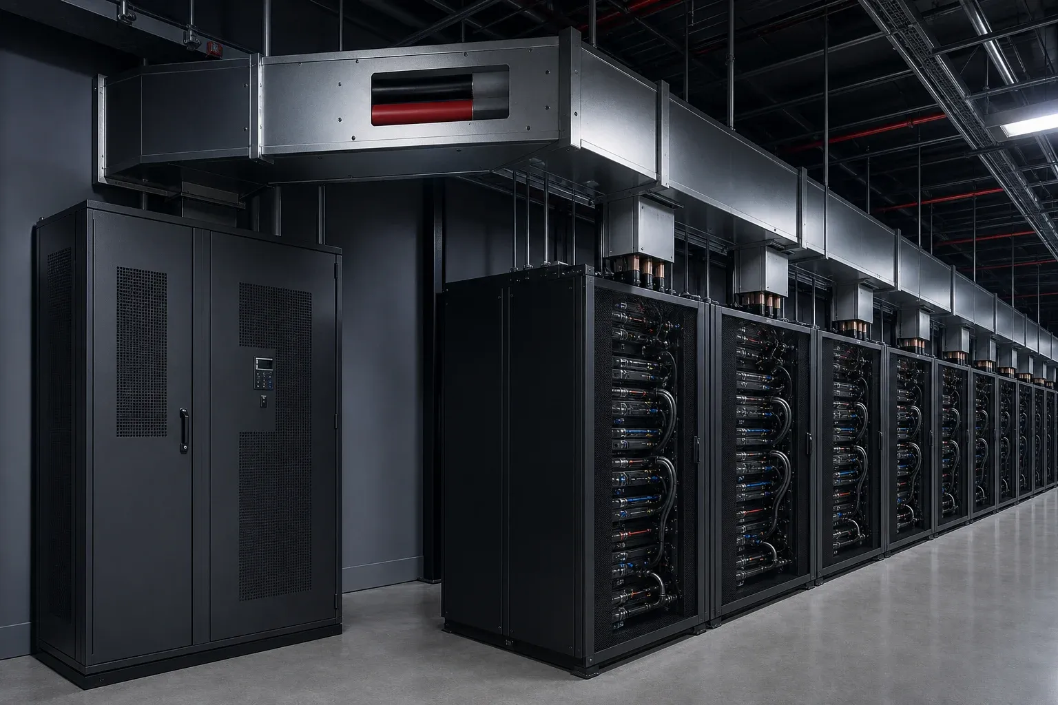
The move toward 800 VDC in AI data centers is primarily a system-architecture response to rack power, not a request for a thicker copper bar. Raising distribution voltage reduces current for the same power, but it also changes insulation, protection, conversion, connectors, maintenance boundaries, and the evidence expected from every supplier in the path.
As of August 24, 2026, 800 VDC should be treated as an emerging architecture with published industry work and active ecosystem development—not as a universal installed standard. Procurement documents must separate current product requirements from roadmap dates.
Why High-Density Racks Are Pushing the Voltage Boundary
Conventional low-voltage distribution becomes difficult as rack power rises: current increases, conductor and connector cross-sections grow, losses and heat concentrate at interfaces, and space for parallel cables or bars disappears. Higher distribution voltage can reduce current at the same power according to the basic relationship P = V × I, before conversion losses and operating margin are included.
That benefit is real but incomplete. Higher DC voltage needs a coordinated approach to insulation, isolation, fault interruption, discharge, polarity, touch protection, monitoring, and service procedures. It also moves conversion losses and failure modes to different locations in the facility.
The NVIDIA developer overview of 800 V HVDC frames the concept around future megawatt-scale rack power. Project designers should use the page as an architecture source, not as a substitute for a site electrical study.
Map the Proposed Path From Facility Power to the Rack
The exact one-line varies, but current published concepts can be understood as four functional zones:
- Utility or campus interface: medium-voltage service, on-site sources, protection, and facility distribution.
- Conversion and row power: equipment converts and conditions power for the row-level DC domain.
- Enclosed 800 VDC distribution: busway or another enclosed conductor system carries power along the row with defined protection and tap-off interfaces.
- Rack power shelf: rack equipment converts 800 VDC to the voltages required by compute, networking, cooling, and control loads.
The NVIDIA 800 VDC architecture hub and its 2026 architecture update describe current terminology, ecosystem work, and intended milestones. Because the roadmap is moving, quote its dates as targets or expectations exactly as published and recheck them before releasing a project specification.
Busway and Busbar Inputs Change Together
Lower current for a given power can reduce some conductor constraints, but voltage-related and fault-related constraints become more prominent. The design input set should cover:
- nominal and maximum operating voltage, transients, and grounding/reference scheme;
- continuous, overload, and fault current at each location;
- insulation system, clearances, creepage, edge geometry, and pollution environment;
- polarity identification and protection against incorrect assembly;
- enclosure, barriers, tap-off access, and discharge behavior;
- joint temperature, contact monitoring, and maintenance access;
- converter ripple and high-frequency current content where relevant;
- expansion, vibration, and tolerance at rack or power-shelf interfaces.
Do not convert “higher voltage means lower current” into a universal copper-saving percentage. Conductor area is only one part of busway mass and cost; enclosure, insulation, protection, conversion, cooling, joints, and redundancy remain.
Terminations Become a System-Level Risk
The best central busway section can be undermined by a poor tap-off or rack connection. At each interface, control contact area, flatness, hardware, polarity, mechanical keying, insulation cutback, touch protection, temperature sensing, and replacement method.
DC fault interruption and stored energy require particular attention. A connector that is safe to unplug in a de-energized procedure is not automatically suitable for load breaking. Protection and maintenance sequences must be defined by the system designer and qualified equipment provider.
For high-frequency power conversion close to the rack, laminated busbar design may become relevant at capacitor and semiconductor interfaces. That component-level technique should not be confused with the long enclosed row busway.
Fabrication Readiness Is More Than Machine Size
Busbar suppliers need controlled drawing revisions, repeatable datums, clean edges, accurate terminals, qualified insulation, and traceable process evidence. They also need to understand which features belong to a prototype and which have reached a released production configuration.
A fabrication-readiness review should ask:
- Can every conductor and insulation layer be inspected against a released drawing?
- Are contact faces and insulation cutbacks controlled from stable datums?
- Are prototype tooling and production tooling equivalent?
- Can the process handle long enclosed-conductor sections and smaller precision terminal parts?
- Are dielectric, thermal, fault, and joint tests allocated to the correct supplier?
- Which design changes require new samples or system-level revalidation?
Precision punching or shearing can support terminal consistency, but it cannot certify an 800 VDC architecture. The switchgear manufacturing solution should be evaluated as one link in the system evidence chain.
Track What Is Settled and What Is Still Open
The Open Compute Project has published a facility LVDC power-distribution white paper and a versioned solid-state-transformer design specification. These documents give engineers a primary-source view of the developing architecture. Version numbers matter: a project should record the exact issue it used and check for later revisions.
Open items can include equipment availability, protection coordination, certification pathways, connector interoperability, cooling interfaces, operational ownership, and local authority approval. “Ecosystem partner” status does not automatically make every component interchangeable or approved for every site.
Keep 800 VDC Separate From the 1500 VDC Roadmap
| Boundary | 800 VDC row/rack discussion | 1500 VDC facility-side discussion |
|---|---|---|
| Primary location | close to high-density rows and racks | broader facility distribution concept |
| Main objective | reduce rack-delivery current and conversion complexity | move more power across facility distances |
| Key interfaces | row power, overhead busway, rack shelf | facility switchgear, conversion, long busway runs |
| Maturity question | component ecosystem and production timing | architecture, protection, and deployment path |
| Procurement owner | rack/power and facility teams together | facility electrical and utility-interface teams |
This is a boundary aid, not a statement that every proposed design follows the same voltage split. The current 1500 VDC busway procurement guide remains focused on facility-side planning, while this page owns the 800 VDC row/rack intent.
Use a Supplier Readiness Checklist
| Area | Evidence before production release |
|---|---|
| Architecture | frozen one-line and named voltage-domain boundaries |
| Electrical inputs | current, fault, transient, grounding, protection, thermal duty |
| Mechanical interfaces | released 2D/3D terminal and enclosure datums |
| Materials | controlled conductor, insulation, finish, and supplier grades |
| Prototype | representative geometry with documented test configuration |
| Production | process capability, inspection plan, traceability, change control |
| Compliance | applicable standards, certification path, responsible authority |
Use this checklist alongside the broader data center switchgear procurement guide. The goal is not to buy “an 800 VDC busbar” quickly; it is to keep architecture, safety, interfaces, and manufacturing maturity synchronized as the ecosystem develops.
Frequently Asked Questions (FAQs)
Why are AI data centers considering 800 VDC distribution?
Rising rack power makes high-current low-voltage distribution harder to package and cool. Raising distribution voltage can reduce current for the same power, but the complete system must address insulation, protection, conversion, connectors, maintenance, and applicable safety requirements.
Is 800 VDC already a deployed data center standard?
It is an emerging architecture and ecosystem rather than a universal deployed standard as of August 2026. NVIDIA and OCP have published architecture and specification work, while component availability, project adoption, certification, and local approval still require project-specific confirmation.
Where does the 800 VDC busway sit in the proposed architecture?
Published concepts place an enclosed DC distribution path at row level between power-conversion equipment and high-density racks. Exact conversion boundaries, protection, tap-off design, and rack interfaces depend on the adopted architecture.
How is 800 VDC different from a 1500 VDC data center busway?
The terms can refer to different voltage domains and locations. Current 800 VDC proposals focus strongly on row-to-rack power for high-density AI systems, while 1500 VDC discussions may address a higher-voltage facility distribution roadmap. The project one-line must define the actual boundary.
What should a busbar supplier verify before quoting an 800 VDC project?
Verify the current path, voltage and transient basis, insulation and edge requirements, fault and protection concept, terminal drawings, polarity, enclosure, cooling, test plan, applicable standards, production status, and authority responsible for approving changes.