
Busbar Hole-to-Bend Distance: Prevent Distortion Before Production
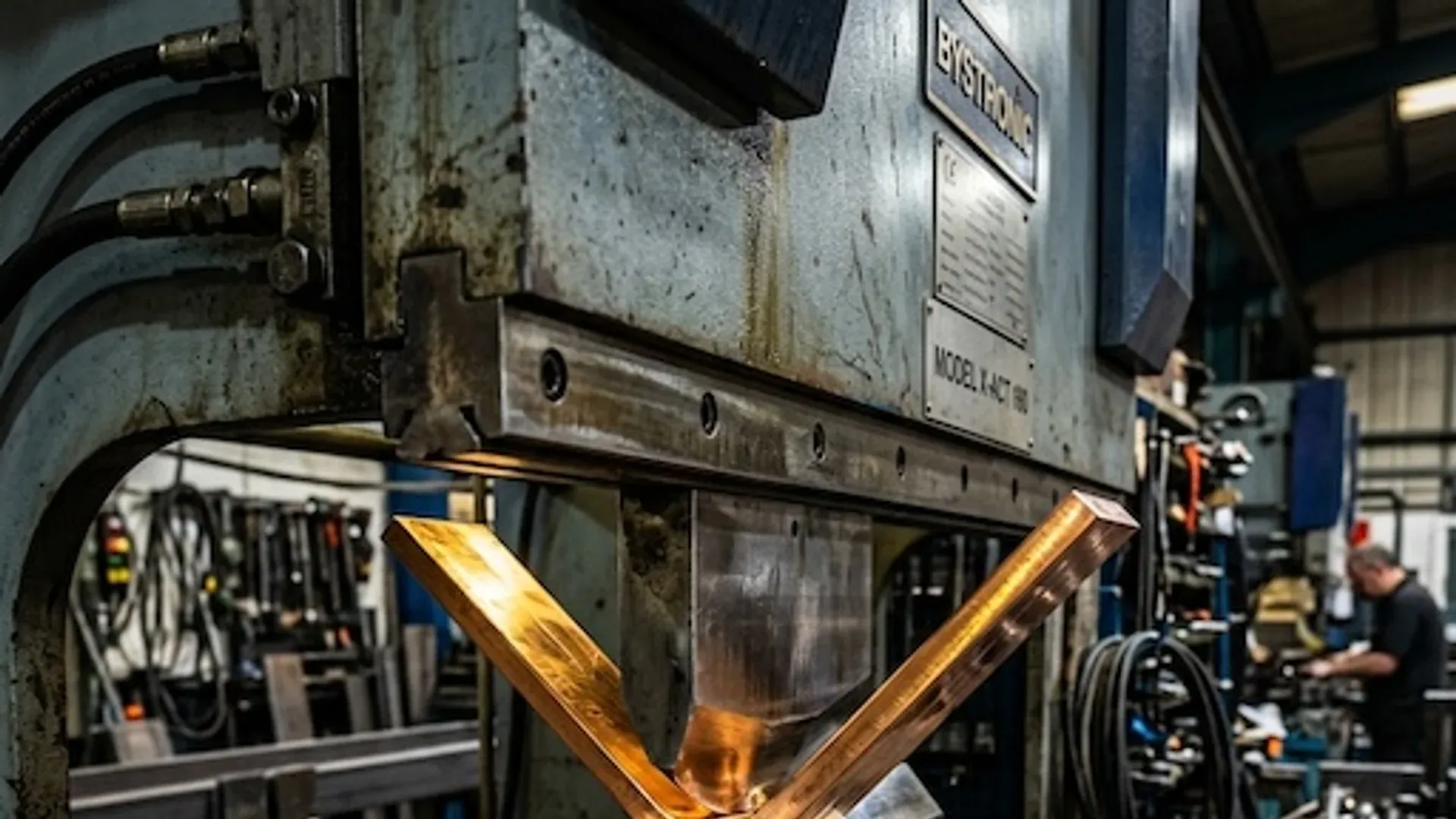
A hole that is correctly located in the flat pattern can become an oval, shifted or tilted feature after bending. The surrounding copper can also lose the flatness needed by a washer, lug or plated contact pad. For that reason, busbar hole-to-bend distance is not merely a drafting clearance; it is the boundary between two manufacturing processes that can interact.
The common response is to copy a multiple of thickness into a design rule. That is useful only when the rule states its material, temper, inside radius, bend method, feature geometry and measurement definition. Without those conditions, the ratio looks precise while leaving the real risk unresolved.
A Single Minimum Distance Cannot Cover Every Busbar
Consider two 8 mm copper bars. One uses a large inside radius in a controlled vertical bend and has a round clearance hole well outside the contact pad. The other uses a tighter offset bend beside a long slot in half-hard material. Equal thickness does not give them equal deformation.
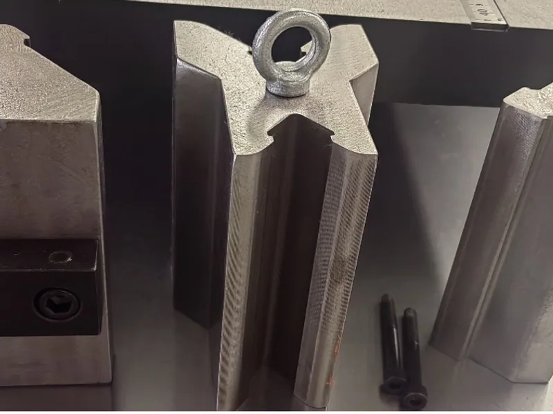
The result can change with:
- alloy, temper, grain direction and lot variation;
- measured thickness and edge condition;
- inside radius, bend angle, open height and sequence;
- punch, V-die, wipe, rotary or other forming method;
- clamp location, tool width and part support;
- round hole, slot, notch or closely spaced pattern;
- acceptable diameter, position, flatness and surface damage.
General sheet-metal suppliers publish their own feature rules. Protolabs, for example, presents sheet-metal design guidelines tied to its service capabilities and material ranges. Such a table is evidence that manufacturability limits are process-specific—not a standard for every thick copper busbar.
Locate the Deformation Zone From the Actual Process
Begin by defining the geometry. A theoretical bend line in a flat model is not the same reference as the inside tangent after forming. “20 mm from bend” could mean hole center to line, hole edge to line, or edge to tangent. Those interpretations produce different remaining ligaments.
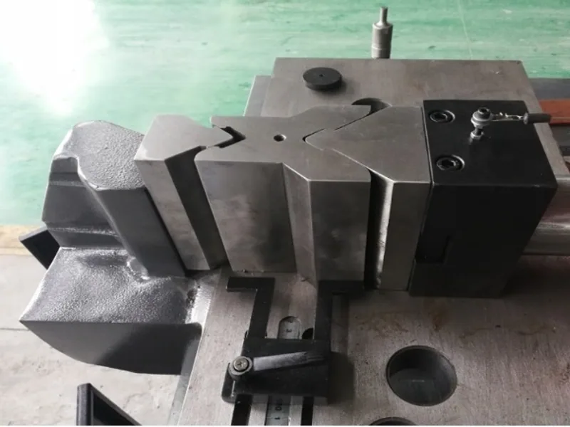
On the drawing and DFM report, show:
- the theoretical bend line or modeled tangent references;
- inside radius and bend direction;
- material side that contacts the tool;
- hole edge and center references;
- tool or clamp keep-out zone;
- the supplier-qualified deformation boundary.
Use the actual tool geometry to estimate where material will be supported, compressed, stretched or dragged. Then confirm with a representative coupon. The industry guide Copper for Busbars provides useful background on copper-busbar forming, but the production tool and specified material condition still need their own validation.
The bend-allowance and verified flat-pattern guide addresses developed length. Hole-to-bend DFM is a different task: it protects a finished feature and its functional neighborhood from the forming operation.
Protect the Electrical and Assembly Functions
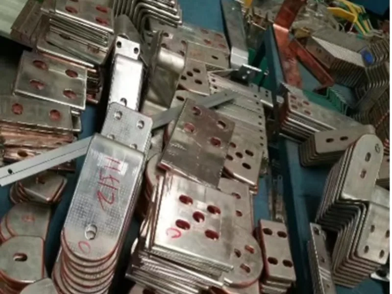
Diameter and true position are only two acceptance characteristics. A connection hole normally belongs to a larger functional area. Review the complete interface:
| Function | What bending can disturb | What to define |
|---|---|---|
| bolted contact | contact-pad flatness, plating, washer seating | pad boundary, flatness, finish and protected zone |
| structural ligament | tearing or excessive thinning between hole and edge | minimum finished ligament based on design loads |
| fastener installation | socket, wrench, washer or nut interference | assembly-tool envelope in the formed condition |
| insulation coordination | movement of conductor toward another potential | finished clearances, creepage path and insulation boundary |
| datum scheme | hole shifts relative to terminal plane | functional datums and formed-part measurement method |
| surface condition | tool marks or cracking near a high-field edge | permitted marks, edge break and inspection method |
Do not let a nominally acceptable hole hide a tilted contact pad. The busbar drawing-tolerances guide explains how to anchor hole patterns and terminal planes to functional datums instead of inspecting every dimension from a sheared edge.
Choose Punch-Then-Bend or Bend-Then-Machine Deliberately
Punching the flat blank first is normally fast and easy to automate. The part lies on a stable plane, nesting is straightforward, and holes can share the same datum system as the cut length. It works well when all critical features remain outside the qualified deformation and clamp zones.
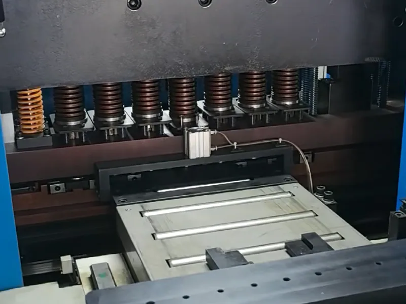
Bending first and machining a final hole later can protect a critical feature from deformation, but it introduces new work. The formed part must be located from a useful datum. Tool access and chip control become harder. Burrs must be removed without rounding a contact face, and the operation must not contaminate an insulated or plated part. Throughput and measurement cost rise.
A third option is to rough the feature before bending and finish it afterward. That can reduce secondary machining load but needs enough stock and a controlled locating method. Whatever sequence is selected, identify which operation establishes the final feature and which drawing revision controls it.
The busbar deburring guide should be part of the plan whenever a critical hole is completed after forming. Burr control is not optional simply because secondary machining solved the position problem.
Replace a Universal Rule With a Supplier Capability Envelope
Create a small qualification matrix around the intended production extremes. Use the specified copper grades and tempers, minimum and maximum thickness, proposed tools and radii, representative hole/slot shapes, and the actual operation sequence. Include features near the proposed limit as well as a safer control position.

Measure before and after bending:
- hole size, roundness or slot profile;
- location relative to the finished datums;
- contact-pad flatness and tool marking;
- ligament width and visible edge strain;
- cracks under the agreed visual or enhanced inspection;
- bend angle and terminal-plane position.
Record every setup variable and sample. The result is not a universal copper rule; it is a capability envelope for a stated material-and-tool combination. Add design margin so ordinary production variation does not sit on the failure boundary.
If a different machine, tool radius, temper or sequence is introduced, decide whether the change remains inside that qualification. The DHAC-BB-H page describes a dedicated bending application, but no product page can validate an unknown customer’s hole layout without the drawing, material and tooling evidence.
Put the Result on the Drawing and Inspection Plan
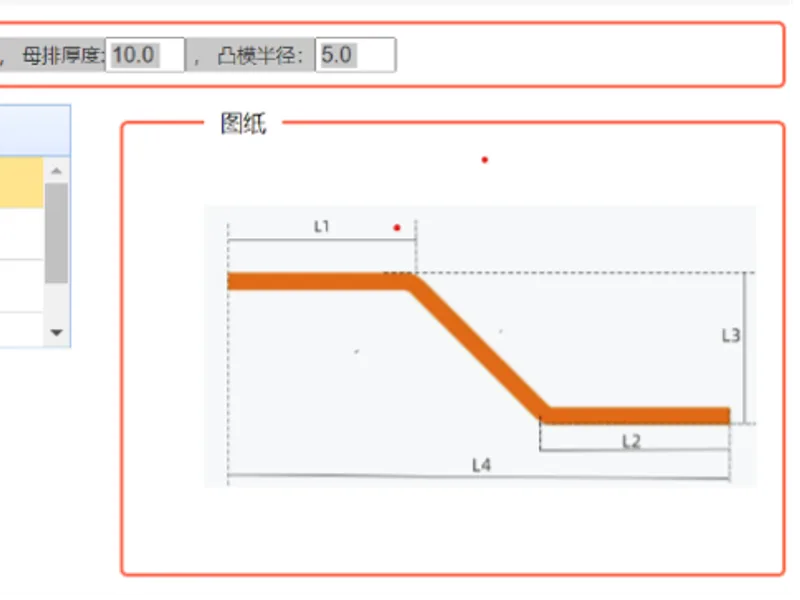
Once validated, translate the process agreement into durable documents. The model or drawing should state the material and temper, thickness, bend radius and direction, critical mark/contact zones, functional datums and finished-feature requirements. Use an unambiguous definition for the hole-to-bend dimension.
The manufacturing router should state the operation order, machine/tool identification, program revision, material-lot control and any first-off coupon. The inspection plan should say whether the hole is measured before forming, after forming, or both—and which result accepts the part.
Avoid burying a critical DFM exception in email. If the supplier accepts a closer feature only with a special tool, bend direction or post-bend operation, place that condition on the controlled quotation and process documentation.
Resolve a Crowded Layout Before It Reaches the Machine
When a feature intersects the qualified zone, the solution is not always to request a tighter machine tolerance. Options include moving the hole, moving or reversing the bend, increasing the inside radius, changing a slot orientation, adding an engineered relief, enlarging the conductor envelope, changing the fastener arrangement, or approving a post-bend finishing operation.
Review the electrical consequences of every change. Moving a hole may reduce contact area or insulation clearance. Adding a relief may change current density or short-circuit mechanical strength. Increasing radius changes envelope and flat length. The designer, assembly engineer and fabricator should close those loops together.
The best hole-to-bend rule is therefore not a single number. It is a clearly measured distance tied to the functional interface, a documented production route, and a capability test that shows the finished busbar—not just the flat CAD file—meets the requirement.
Frequently Asked Questions (FAQs)
Is there one universal minimum hole-to-bend distance for copper busbars?
No. The safe distance depends on how distance is defined, material thickness and temper, inside radius, bend angle and direction, hole shape and size, tooling and clamping, operation sequence, and the permitted hole and contact-pad distortion.
Where should busbar hole-to-bend distance be measured from?
The drawing must state the references. Useful definitions include hole edge or center to the theoretical bend line, tangent point, or boundary of a supplier-qualified deformation zone. A number without those references is ambiguous.
Why can a hole become oval when a busbar is bent?
Material near the bend undergoes tensile and compressive strain and can also be dragged by the tooling or clamp. If a hole or slot intersects that deformation zone, its diameter, shape, position, flatness, and surrounding contact surface can change.
When should a busbar be bent before its final hole is machined?
Bend-first processing can be appropriate when a critical hole cannot be kept outside the deformation zone and a reliable post-bend datum and machining setup exist. The choice must also account for access, burr removal, contact-face protection, inspection, cost, and throughput.
DHAC-BB-H Servo-Hydraulic Busbar Bender
Discover details, parameters, standard dies packages, and factory quotes.