
Transformer Shortage 2026: How Busbar Fabrication Capacity Affects Delivery
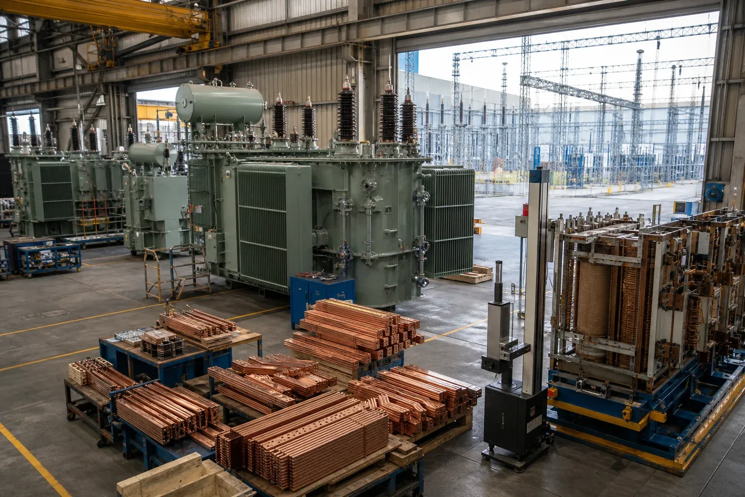
The transformer shortage is not a copper-busbar shortage. It is a multi-stage supply problem involving demand growth, ageing infrastructure, electrical steel, conductors and components, skilled labor, factory and test capacity, qualification, order queues, and long project approvals. Busbar fabrication matters because it can become one avoidable constraint inside that larger system.
The practical response is not to claim that one new machine solves transformer lead time. It is to identify repeated conductor families, freeze interfaces earlier, validate difficult parts before assembly, and add capacity at the operation that the actual product mix constrains.
Read the 2026 Evidence Carefully
The US Department of Energy transformer program describes supply-chain constraints, long lead times, and collaboration intended to reduce production time and unnecessary variation. A March 2026 DOE webinar also discussed resources developed to improve interchangeability communication and reduce excessive utility stock-keeping-unit variation.
The Government Accountability Office report on transformer reserves adds an independent federal view of supply resilience. Meanwhile, a June 2026 Federal Register request for information asked how the 2024 efficiency final rule interacts with domestic manufacturing capacity and supply-chain resilience.
That 2026 document is an RFI, not a new final rule. It states that the April 2024 final rule’s amended standards have a 2029 compliance date. Articles and procurement reports should keep those legal statuses separate.
The Bottleneck Is a System, Not a Single Material
Different transformer classes have different constraints, but the system can include:
- grain-oriented or amorphous electrical steel and core production;
- copper or aluminum windings, leads, busbars, and terminals;
- tanks, bushings, tap changers, protection and control components;
- design and customer approval capacity;
- winding, drying, oil processing, assembly, and test bays;
- skilled manufacturing and test labor;
- utility or EPC specifications with many low-volume variants;
- logistics for large, heavy, or project-specific equipment.
DOE’s R&D efforts to address transformer supply show why demand, materials, manufacturing, and innovation have to be considered together. A capacity project that improves punching but leaves drawing approval or final test unchanged may not improve shipment dates.
Find Where Busbar and Lead Fabrication Enter the Critical Path
Transformer conductors can range from simple drilled straps to thick bars with offsets, edge bends, twists, plated interfaces, and tight terminal relationships. They become schedule-critical when:
- coil, bushing, tap, or enclosure interfaces change late;
- the final formed datums are not defined on the drawing;
- a complex part needs custom tooling or a manual operation;
- holes are referenced to a flat blank rather than the final terminal planes;
- an outside finish process lacks reserved capacity;
- fit is first checked at final transformer assembly;
- rework authority and acceptance criteria are unclear.
The dedicated transformer busbar fabrication guide covers the geometry. Capacity planning should use that geometry to classify parts before buying equipment.
Standardize Repeated Parts Without Freezing Bad Designs
Useful standardization occurs at stable interfaces: common terminal palms, hole families, material widths, bend radii, finish callouts, drawing templates, and inspection gauges. It reduces setup and approval work while keeping project-specific conductor lengths or offsets configurable.
Do not standardize by deleting critical electrical or mechanical differences. Two parts with similar outlines may carry different current, experience different fault force, use different insulation, or connect to different terminals. Engineering must define the safe family boundary.
A controlled part-family record should list the master design, permitted variables, tooling, material range, inspection fixture, and changes that require requalification.
Size Capacity Around Part Families and Operations
Start with a transparent load model:
required hours = quantity × (run time + average handling time) + setups + expected inspection/rework
Then compare required hours with demonstrated available hours at each operation. Include operator availability, preventive maintenance, material handling, tool changes, and yield. Catalogue strokes per minute should not be used as finished-parts-per-shift without a representative trial.
| Part family | Main operations | Likely constraint to test | Alternate route |
|---|---|---|---|
| Straight drilled or punched links | cut, punch, deburr | hole program and material handling | second punch/shear cell |
| Repeated flat/edge bends | punch, bend, inspect | setup and springback by material lot | family tooling and stored program |
| Complex twist/offset conductors | multiple forming and fit check | special tooling and manual alignment | early batch, dedicated fixture |
| Plated terminal parts | form, finish, protect, inspect | outside-process queue and damage | reserved capacity or approved second source |
A multi-function busbar processing machine can be useful for a mixed part family, but it should be evaluated against the actual range of punching, shearing, flat bending, and edge bending. Complex 3D conductors may still need specialized tooling or a separate route.
Freeze Drawings and Acceptance Criteria Earlier
Long-lead material should not be ordered against an unstable interface without a controlled risk decision. Establish a release sequence: preliminary interface, prototype, first article, production release, and change cutoff. Each stage should state what can still change and who pays for scrap or retesting.
Acceptance should use final assembly datums. A fit-up gauge representing the transformer terminals can find alignment errors before the conductor reaches the main assembly bay. The inspection report should link the gauge or measurement program to the same drawing revision used for production.
Evaluate Supplier and Equipment Resilience
Resilience is not merely having two vendors. It includes transferable drawings, common material grades where permitted, spare tools, software backups, maintenance capability, trained operators, and an approved alternate process for the bottleneck.
Before adding equipment, use the megaproject supplier-qualification guide to verify capacity evidence. Before shipment, apply a busbar-specific FAT and SAT protocol using representative transformer parts.
Use a 90-Day Risk-Reduction Sequence
Days 0–30: make the load visible
Clean the part master, group conductor families, record drawing stability, route each family, and calculate the load at every operation. Identify which shortages are data problems and which are physical capacity problems.
Days 31–60: validate the family controls
Release standard interfaces, trial the difficult parts, create fit-up gauges, confirm finish capacity, and document the measurement method. Resolve recurring nonconformances before scaling.
Days 61–90: secure the bottleneck
Add shifts, tooling, maintenance, an alternate supplier, or equipment only where the evidence justifies it. Tie the action to demonstrated throughput and quality, then update the production plan with actual results.
For transformer and busduct manufacturing, this sequence will not remove global supply constraints. It can prevent an internally controllable conductor delay from adding to them.
Frequently Asked Questions (FAQs)
What is causing the transformer shortage in 2026?
The evidence points to a system of constraints rather than one cause: demand growth, ageing grid assets, limited manufacturing capacity, electrical-steel and component supply, labor, factory expansion time, qualification, and long testing and procurement cycles. The mix varies by transformer class and region.
How long are transformer lead times?
There is no reliable universal lead time. It varies by transformer type, rating, design, materials, factory, testing, order queue, approvals, and destination. Buyers should request a dependency schedule with dates for design release, materials, assembly, tests, and shipping.
How can busbar fabrication delay transformer assembly?
Busbars and lead conductors can become late when terminal drawings are not frozen, thick or three-dimensional parts require special tooling, finishes add outside processing, or fit-up is discovered only at final assembly. Part-family planning and early first-piece checks reduce this risk.
Can standardizing transformer busbars reduce delivery risk?
Yes, when repeated interfaces and part families are genuinely equivalent. Standardization can reduce unique programs, tooling, material and inspection work, but it must not override electrical, thermal, clearance, or terminal requirements.
What data is needed before adding busbar capacity?
Collect part-family demand, material and size range, route by operation, setup and run time, yield and rework, bottleneck utilization, finish and inspection time, drawing stability, and required delivery dates. Size capacity from this mix rather than a single machine cycle rate.
DH303-8P 3-in-1 CNC Busbar Processing Machine
Discover details, parameters, standard dies packages, and factory quotes.