
Busbar Drawing Tolerances: Datums, Hole Position, and Bend Inspection
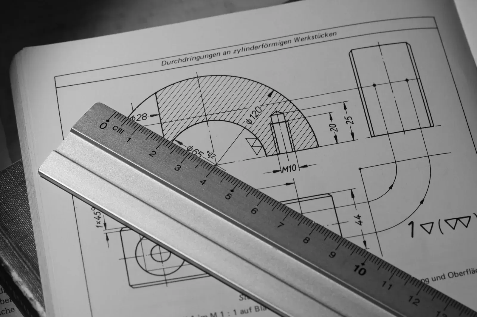
A busbar drawing should tell manufacturing how to produce a part that assembles and tell inspection how to prove it. A drawing fails that task when it tightly tolerances every blank dimension but leaves the final terminal planes, contact faces, or hole relationship ambiguous.
The solution is not a universal “busbar tolerance” table. Begin with the surfaces and features that locate the conductor in the assembly. Build a functional datum system, dimension the formed result, separate process controls from acceptance characteristics, and agree how each critical feature will be measured.
Start With the Surfaces That Locate the Busbar in the Assembly
Trace how the installer constrains the part. One broad terminal face may establish the primary plane. A mounting hole or pin may locate the part in two directions. A slot may deliberately allow movement in one direction. An edge, stop, or second terminal may resolve the remaining orientation.
Those relationships should drive the datum scheme. Do not choose an as-sheared edge as the primary datum merely because it is easy to place against a caliper if the assembly actually locates from the terminal face and hole pattern.
For each candidate datum, ask:
- Is it stable enough to contact a fixture or measurement system?
- Does it exist in the condition being inspected?
- Will plating, masking, or insulation change the surface?
- Does it reproduce the way the part is constrained in service?
- Can both supplier and customer establish it consistently?
The ASME Y14.5 standard page describes a common language for communicating dimensional and geometric requirements. Use the drawing standard specified by the project, and do not mix symbols or interpretations from different systems without declaring them.
Dimension the Finished Function, Not Only the Flat Blank
Blank length, punched coordinates, and bend-line marks are useful manufacturing controls. They do not necessarily describe the final geometry. Copper stretches and compresses through the bend, springback changes the unloaded angle, and several bends can accumulate into a terminal-plane error.
Keep process dimensions where they help manufacturing, but distinguish them from final acceptance. A drawing or controlled inspection model should identify final hole positions, terminal-plane separation, offset, overall envelope, and clearances in the formed condition.
The bend allowance and K-factor guide explains how a qualified flat pattern is developed. Once that pattern is released, do not let an inspector reject the finished busbar solely because a reverse-calculated blank dimension differs from a generic K-factor. Inspect the functional result and separately manage the approved process data.
For complex twist bends or offsets, a 3D model can clarify the intended shape, but the controlled drawing still needs to state which file governs, the revision, units, datums, and acceptance characteristics. A model without an inspection definition leaves the same ambiguity in a different format.
Control Hole Patterns From a Common Datum System
Chained hole dimensions can accumulate tolerance across a long part. If each hole is located from the previous one, the last hole may drift substantially relative to the terminal datum even though every local pitch passes. Where function requires the complete pattern to align with an assembly, locate it from a common datum scheme.
Basic dimensions and a position requirement can communicate the allowed zone for hole axes relative to datums when the project’s drawing standard supports that approach. The designer must still define hole size, any material-condition modifier, and the datum references correctly. Do not add a position symbol as decoration while retaining conflicting plus/minus coordinates.
Slots need an intentional role. A slot may absorb assembly variation or thermal movement, but it should not conceal an undefined datum strategy. Specify its orientation, size, end geometry, and relationship to fixed holes. Protect minimum material at edges and between features using the actual mechanical and electrical design requirements, not a generic ratio copied from another part family.
Inspection should establish the same datums as the drawing. Measuring every hole from the nearest sheared edge can give passing local numbers while missing a displaced pattern. A fixture, vision system, height gauge, or coordinate measurement may be appropriate depending on tolerance, size, and volume.
Specify Bend Results That Can Be Measured
An angle callout alone rarely controls a formed busbar. Add the relationships that determine installation: bend location, inside radius where functional, leg length, offset, parallelism or orientation of terminal faces, and final envelope. State whether dimensions apply in the free state or in a defined restraint fixture.
Choose accessible measurement surfaces. A short leg with a rounded corner may not provide a reliable angle reference. In that case, a fixture that locates the terminal faces can better represent assembly fit than a handheld protractor.
For multiple bends, identify the sequence-sensitive characteristics. A machine can produce each angle within its assigned tolerance while the total offset fails because bend locations and material behavior accumulated. Use a first-article report to capture both individual operations and the final datum relationships.
The complete busbar fabrication process shows why drawing review, punching, bending, finishing, and inspection must share one datum strategy instead of optimizing each operation separately.
Treat Contact Faces, Coating, and Insulation as Functional Features
Electrical contact zones need more than an overall part outline. Define their boundaries, masking or plating requirements, permitted surface condition, and any flatness or finish requirement derived from the joint design. Do not assign a severe whole-part flatness tolerance when only a local terminal zone controls contact.
State whether dimensional requirements apply before or after plating. A coating can affect hole size, local thickness, contact surfaces, and fixture contact. Insulation drawings should define cutbacks, keep-out zones, overlap, edge coverage, and the reference from which those features are located.
Marking also belongs in the drawing package when orientation or traceability matters. Define a zone that will not damage contact surfaces, insulation interfaces, or bend areas. Identify the required content—such as part number, revision, and lot link—without forcing a marking method that conflicts with finish requirements.
Build the Drawing Package and First-Article Plan Together
A release package for a fabricated busbar normally needs more than a dimensioned view:
| Information | Why it matters |
|---|---|
| Material grade, temper, section, and governing specification | affects conductivity, forming, springback, and records |
| 2D drawing and controlled 3D model | defines dimensions, datums, and intended geometry |
| Finish, contact zones, and insulation details | controls interfaces after fabrication |
| Critical-to-function feature list | focuses process control and inspection |
| Measurement method or fixture concept | ensures requirements are practically verifiable |
| First-article report format | aligns supplier and customer evidence |
The first article should record actual results, not only checked boxes. For a datum-dependent hole pattern, retain coordinate results or a fixture outcome. For terminal planes, record the agreed offset and orientation method. For coating or insulation, record the correct post-process characteristics.
Use the finished copper busbar inspection checklist to connect dimensional evidence with material identity, edge quality, finish, cleanliness, and packing.
Run a DFM Review Before Freezing Tolerances
Bring design, assembly, fabrication, coating, and inspection into one review. Ask the manufacturer to identify features that require special tooling, secondary machining, dedicated fixtures, or post-plating inspection. Ask assembly engineering which dimensions actually consume clearance or alignment margin.
A hole beside a bend requires its own process boundary because its finished shape and contact pad can change even when the flat coordinates are correct. Use the busbar hole-to-bend DFM workflow to define the distance reference, qualified deformation zone, operation order and coupon evidence instead of copying a universal thickness ratio.
Do not loosen a functional requirement merely because the current process cannot hold it. First determine whether the datum or measurement method is wrong, whether the design can add locating freedom, or whether a different route is required. Conversely, do not preserve a tight legacy tolerance if no interface uses it.
When evaluating a multi-function line such as the DH303-8P busbar processing machine, submit representative drawings and require sample evidence. A machine category cannot guarantee an undefined drawing tolerance.
A good busbar drawing is a negotiated technical contract. It protects electrical and mechanical function, gives manufacturing enough freedom to build economically, and gives inspection a repeatable method for deciding whether the finished part belongs in the assembly.
Frequently Asked Questions (FAQs)
Should every dimension on a busbar drawing have a tight tolerance?
No. Tighten the characteristics that control fit, electrical contact, clearance, tooling, or safety, and allow appropriate freedom elsewhere. Unnecessary tight tolerances increase inspection and scrap without improving the assembly.
Should a bent busbar be inspected from the flat blank or the finished part?
Both may need controls, but final acceptance must protect the formed part's functional datums, terminal planes, hole pattern, and envelope. Blank dimensions are process controls and do not by themselves prove final assembly fit.
How can a drawing prevent accumulated error across several busbar holes?
Locate the pattern from a common functional datum system rather than chaining every pitch from the previous hole. Define the applicable position or coordinate requirements and use an inspection method that reproduces the assembly reference.
Is there one standard dimensional tolerance for all copper busbars?
No. Appropriate tolerances depend on material form, part size, manufacturing route, connection design, enclosure clearances, coating, volume, and inspection capability. The drawing must derive them from the actual function and qualified process.
DH303-8P 3-in-1 CNC Busbar Processing Machine
Discover details, parameters, standard dies packages, and factory quotes.