
Copper Busbar Inspection Checklist for Finished Parts and Incoming Acceptance
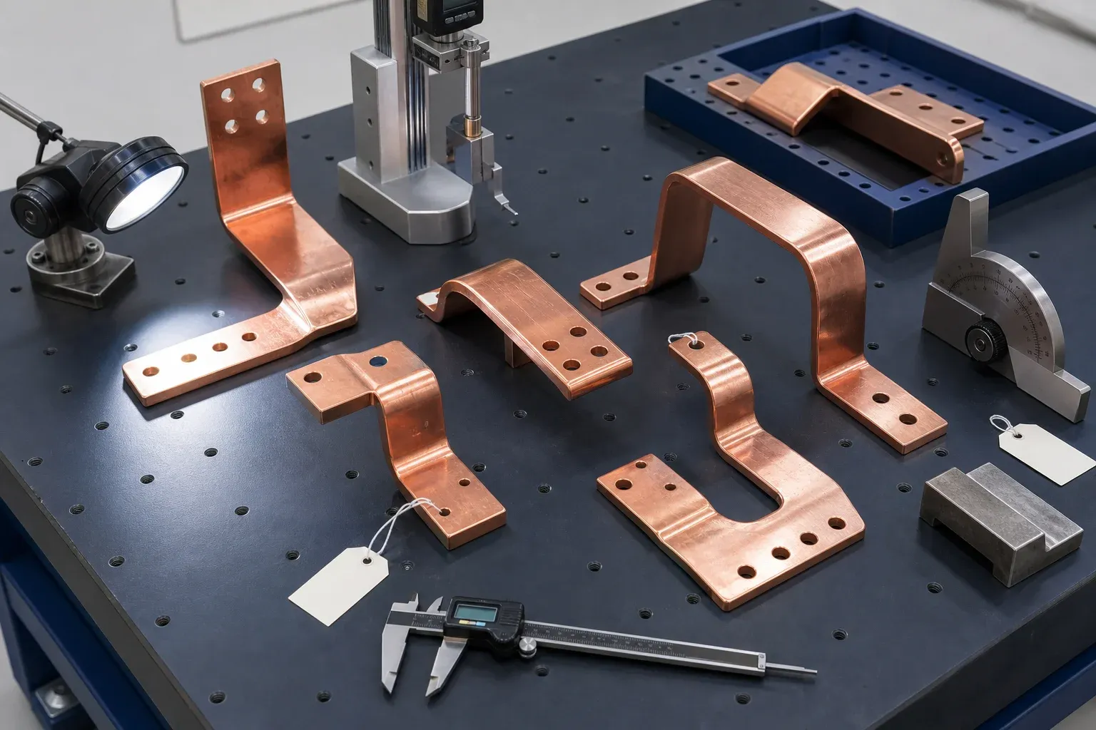
This checklist is for newly manufactured copper busbars at final inspection or incoming receipt. It is not an in-service maintenance interval, an infrared survey procedure, or a replacement for the drawing. Every acceptance result must point back to the purchase order, released specification, or applicable project standard.
The inspector’s job is to verify identity, fit, functional surfaces, finish, and records without inventing missing tolerances. When a requirement is unclear, quarantine the part and obtain an engineering decision before rework or assembly.
Establish the Inspection Basis First
Before opening the package, confirm the purchase order, part number, drawing and revision, material and finish, required documents, quantity, lot definition, and sampling plan. Identify the characteristics critical to safety, electrical interface, and assembly fit.
The inspection plan should state who can accept, reject, approve rework, or authorize use-as-is. It should also address measurement uncertainty where the tolerance approaches the capability of the instrument or method.
Calibration status is necessary but not sufficient. NIST’s metrological traceability policy explains that a result needs a documented, unbroken calibration chain and that traceability by itself does not guarantee fitness for the measurement task. The inspection plan must therefore match method, resolution, and uncertainty to the actual tolerance.
Never measure against an uncontrolled screenshot or a superseded drawing. If the supplier and buyer use different revision systems, include a cross-reference on the order and report.
Verify Documents, Material, and Traceability
At receipt, check:
- packing list and part quantity;
- part number, orientation, and drawing revision;
- material certificate when required;
- conductor grade and condition as specified;
- thickness, width, and other stock characteristics;
- lot or heat identity where required;
- outside-process certificate for plating or insulation when specified;
- first-piece or final inspection report;
- approved deviation or concession references.
Positive material identification is not automatically required for every copper part. Use it only when the contract, risk, or quality plan requires it. Traceability strength should match the consequence of mixing material or revisions.
Check Blank Size, Holes, Slots, and Edges
Measure from the drawing datums. Confirm overall length and width, hole and slot size, pitch, edge distance, countersink or emboss features where applicable, and orientation. Inspect both sides for burrs, rollover, deformation, cracks, and tool marks.
When edge defects recur, the busbar deburring and cleanliness guide explains how to trace the cause, select a finishing method, and protect contact faces. A smooth-looking edge still needs to meet the drawing and inspection method.
Look beyond each individual dimension. A hole pattern can pass internally but be shifted relative to the final end or bend. An assembly gauge or datum-based measurement captures the functional relationship.
For parts produced on a CNC punching and shearing workstation, the report should still use the buyer’s drawing and agreed measuring method, not only the machine’s displayed coordinates.
Measure Bend Geometry and Final Fit Datums
Inspect bend angle, location, radius when controlled, offset height, leg length, parallelism, terminal-plane orientation, and overall envelope. Edge bends and twists may need a fixture or 3D method because a handheld angle gauge cannot describe the complete geometry.
Support the part consistently. Long bars can sag, and a compliant part can be forced into a passing condition. The inspection setup should represent the intended assembly support or the drawing’s free-state definition.
Use the DHAC-BB-H bending equipment page as product context, not as a source of universal part tolerance. Springback and final geometry remain material-, tool-, and drawing-dependent.
Inspect Contact Surfaces, Plating, and Insulation
Contact faces should be clean, protected, and free of damage beyond the permitted workmanship standard. Confirm masking or insulation cutback dimensions, coating coverage, plating appearance, edge integrity, and any specified thickness or adhesion records.
Do not assume that a bright surface is electrically acceptable or that discoloration is automatically a failure. Compare the actual condition to the approved finish specification. The tin and silver surface-treatment guide explains finish selection; a separate contact-resistance guide covers the assembled joint test.
Insulation inspection should look for cracks, voids, lifting, wrinkles, edge thinning, contamination, and incorrect cutbacks. Electrical testing, when required, follows the project procedure rather than a visual checklist.
Confirm Marking, Cleanliness, and Packaging
Part marking should provide the identity and orientation required by the drawing without damaging a functional surface. Confirm phase or polarity identification where specified, but do not accept color alone as traceability.
Packaging must prevent bars from rubbing, bending, corroding, or contaminating contact areas. Use separators, end protection, moisture control, and rigid support as needed for the geometry and route. Check that labels remain connected to the correct lot after partial unpacking.
When parts will wait in a warehouse, move through work in process, or travel in export packs, use the separate copper busbar storage and packaging plan to control condensation, level support, surface-compatible wrapping, lot separation and staged inspection.
Record Nonconformance and Control Disposition
When a characteristic fails, record the measured value, requirement, method, location, photograph if useful, quantity affected, and lot. Segregate the parts. The disposition can be reject, rework, repair, or use-as-is only through the authorized process.
Rework needs a controlled method and reinspection. Enlarging a hole, flattening a bend, polishing a contact face, or repairing insulation can change electrical, mechanical, or finish behavior. An operator’s ability to make the part fit is not approval.
The broader supplier traceability and factory-audit protocol addresses system controls; this checklist remains focused on the received or finished part.
Use This Finished-Part Checklist Structure
| Item | Requirement to record | Suggested method | Report field |
|---|---|---|---|
| Identity | PO, part, drawing, revision, lot | document and marking review | status and discrepancy |
| Material | grade, condition, section, certificate | certificate plus calibrated measurement | result and certificate ID |
| Blank geometry | length, width, squareness where critical | caliper, rule, height system, CMM | value and tool ID |
| Holes and slots | size, pitch, edge distance, orientation | plug/pin gauge, caliper, CMM, fixture | value/status |
| Edges | burr, sharpness, cracks, deformation | visual/tactile and defined gauge | defect location |
| Bends | angle, location, offset, terminal plane | angle system, height gauge, fixture, CMM | value/status |
| Contact faces | flatness, cleanliness, finish, protection | visual and project-defined measurement | status/lot |
| Plating/insulation | coverage, cutback, damage, specified process result | visual plus specified test | certificate/result |
| Marking/packing | identity, orientation, protection | visual review | status |
| Release | sample/100%, NCRs, approvals | report review | inspector/date/disposition |
Sampling is a planned decision, not a blank filled after measurement. Increase control after a setup, material, drawing, tool, supplier, or process change. Reduce it only when the quality plan and demonstrated capability permit.
Keep the Checklist Connected to the Process
The inspection report should feed production improvement. Repeated hole shift points to program or datum control; repeated edge damage may point to tooling or handling; unstable bend position may point to material, setup, or springback control. Use the complete busbar fabrication process to locate the defect at the step where it is cheapest to prevent.
For machine acceptance, use a different document: the CNC busbar machine FAT and SAT protocol verifies equipment capability and handover rather than accepting a normal production lot.
Frequently Asked Questions (FAQs)
What should be checked on a finished copper busbar?
Check document and revision identity, material and lot, section and overall dimensions, holes and slots, edges and burrs, final bend datums, contact surfaces, plating or insulation, marking, cleanliness, packaging, and required inspection records.
How are busbar hole position and bend angle inspected?
Measure from the drawing datums with a calibrated gauge, height system, fixture, CMM, or other agreed method. Evaluate holes and bends in the final part relationship, because individually correct features can still create an assembly mismatch.
Should every busbar be measured?
Not every characteristic always needs 100 percent measurement. Sampling should reflect drawing criticality, process capability, batch size, tool wear, change history, and contract requirements. Safety- or fit-critical items may require full inspection.
How are plating and insulation defects documented?
Record the part and lot, drawing area, defect type and size, photograph with scale where useful, applicable requirement, result, and disposition. Do not repair a contact finish or dielectric covering without an approved process and reinspection.
What information belongs in a busbar inspection report?
Include part, order, drawing and revision, lot and quantity, characteristic and specification reference, method, measuring-equipment ID, sample size, result, status, inspector, date, and any nonconformance or authorized deviation reference.
DHCNC-BP-60 CNC Punching & Shearing Workstation
Discover details, parameters, standard dies packages, and factory quotes.