
Busbar Insulation Methods: How to Select Heat-Shrink, Epoxy, and Air-Insulated Designs
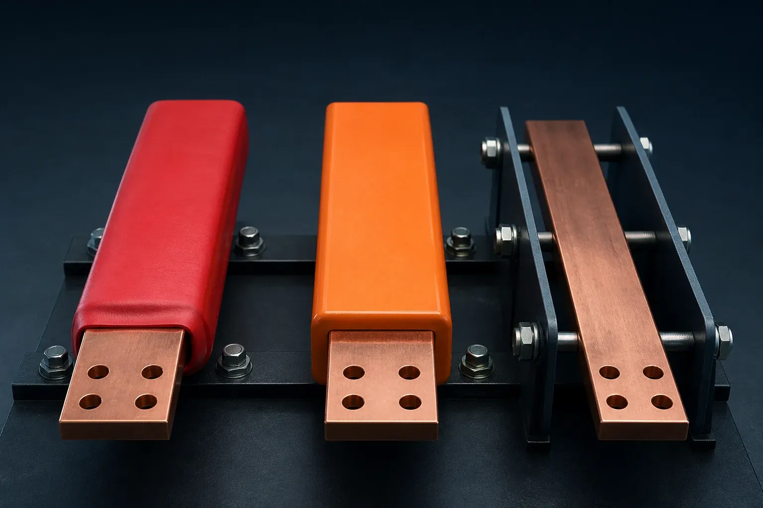
Busbar insulation is a system decision, not a material-shopping exercise. Heat-shrink tubing, epoxy or powder coating, molded boots, barriers, and open-air spacing solve different problems. Selecting one by voltage alone can leave unresolved issues at joints, bends, edges, maintenance points, and the surrounding enclosure.
The correct sequence is to define the protective function, establish the assembly’s electrical and environmental requirements, then select and validate a construction. The busbar drawing must also show where insulation starts and stops, because the best dielectric material still fails when it covers a bolted contact face or becomes thin at a sharp bend.
Define the Insulation Function Before Choosing a Material
An insulation request may be trying to achieve one or more of the following:
- prevent accidental contact with an energized conductor;
- reduce the likelihood or consequence of a phase-to-phase fault;
- support a compact assembly while maintaining the required dielectric performance;
- protect a conductor from contamination, moisture, or handling damage;
- identify phases or polarity;
- provide localized protection at a terminal, bend, or complex connection.
These functions are not interchangeable. A colored sleeve may improve identification but not satisfy the required dielectric test. A coating may reduce exposure but not eliminate clearance and creepage requirements elsewhere in the assembly. An air-insulated conductor can be appropriate when enclosure access, spacing, barriers, and supports are properly controlled.
The assembly standard and project specification remain the governing design inputs. IEC 61439-1:2020, for example, provides the general-rules context for IEC low-voltage assemblies; it does not turn one insulation product into a universal solution.
Compare the Four Common Approaches
| Approach | Where it can work well | Main limitations | Inspection focus |
|---|---|---|---|
| Air spacing with barriers | Accessible assemblies with controlled geometry and enclosure protection | Requires space and disciplined assembly; exposed surfaces remain | Clearances, barriers, supports, access control |
| Heat-shrink tubing | Regular bar shapes, color coding, localized or replaceable coverage | Edge thinning, wrinkles, cutback control, limited fit around complex geometry | Recovery, overlap, surface damage, edge and terminal cutbacks |
| Epoxy or powder coating | Complex formed shapes and continuous coverage | Adhesion, voids, edge thickness, masking, repair process | Coverage, cure, adhesion, thickness if specified, dielectric tests |
| Molded boots and sleeves | Terminations, joints, elbows, and serviceable local protection | Component fit, retention, ageing, interface gaps | Correct part, seating, retention, access and damage |
The IEC 60684-3-283:2019 product standard page describes a category of heat-shrink tubing intended for busbar insulation. It is useful when qualifying that product type, but it does not define the complete switchgear or busduct insulation system.
Select by Electrical, Thermal, and Environmental Conditions
Start with the voltage system, transient or impulse requirements, pollution conditions, installation altitude, conductor temperature, ambient temperature, enclosure ventilation, and fault-protection strategy. Then add the environmental and maintenance requirements: humidity, condensation, salt, dust, chemicals, UV exposure, cleaning method, inspection access, and planned service life.
Thermal behavior is easily overlooked. A covering changes heat transfer around the conductor. The allowable conductor temperature is not simply the insulation material’s headline temperature rating; joints, terminals, surrounding parts, ageing, and assembly temperature-rise verification all matter. The finished assembly needs to be assessed in its real enclosure and duty, not only as an isolated coated strip.
Fire and smoke requirements can also be application-specific. Use the exact supplier datasheet and the project’s applicable standard. Do not infer flame performance from color, thickness, or the generic term “epoxy.”
Sequence Punching, Bending, Plating, Masking, and Insulation
For most rigid copper parts, the production route is planned so that high-strain metalworking is completed before the final dielectric covering:
- verify material and blank datums;
- punch or machine holes and slots;
- shear and form the final geometry;
- deburr, clean, and inspect the copper;
- apply plating where the design requires it;
- mask contact faces and other controlled areas;
- apply heat-shrink, coating, or molded insulation;
- inspect cutbacks, coverage, edges, and finished geometry;
- perform project-defined dielectric or process tests.
The exact order can change. A plated part may require special handling during bending, which is why the guide to processing tin-plated busbars without coating damage treats that route separately. What should not happen is an undocumented secondary bend that stretches a finished coating past its validated strain.
Design Terminations and Inspection Windows Before Coating
The busbar drawing should identify every functional surface that must remain accessible: bolted overlaps, ground connections, connector interfaces, test points, sensor positions, labels, and areas needed for assembly tools. The insulation cutback should be dimensioned from a stable datum, not left to the operator’s judgment.
At a bolted joint, the clean contact surface and the insulated region have competing needs. The contact face must remain free of dielectric material and damaging contamination, while the exposed area around it should not be larger than the approved design permits. A masking fixture or repeatable cutback gauge is usually more reliable than visual estimation.
Maintenance affects the choice too. A molded boot that can be removed and reseated may suit a serviceable terminal. A permanent coating may be appropriate where access is not expected, provided the design includes a repair and inspection method for manufacturing defects.
Verify the Finished Insulation System
No single inspection catches every failure mode. A practical control plan combines process records and finished-part checks.
| Check | Typical defect found | Acceptance basis |
|---|---|---|
| Visual coverage | missed area, wrinkle, bubble, contamination | Workmanship standard and approved sample |
| Edge and bend review | thinning, crack, lifting, sharp-edge damage | Drawing and material process specification |
| Cutback measurement | contact area partly covered or overexposed | Controlled drawing |
| Thickness or continuity | uneven coating or process drift | Qualified coating procedure, when applicable |
| Adhesion or cure evidence | delamination or incomplete process | Supplier/process specification |
| Dielectric test | system-level insulation weakness | Project test plan and applicable standard |
Testing needs defined electrodes, voltage, duration, environment, and acceptance criteria. A pass on a flat coupon cannot automatically validate a complex bend or assembled joint. First-piece approval should therefore use the real geometry or a representative worst-case feature.
For finished assemblies, keep the two common electrical checks separate: an insulation-resistance reading is not a substitute for a dielectric withstand proof test. The busbar insulation-resistance and hipot test plan defines the test boundary, safe discharge, comparable records and failure investigation without assigning a universal test voltage.
Use a Selection Matrix Instead of a Universal Ranking
| Project condition | Likely shortlist | Questions that decide the choice |
|---|---|---|
| Spacious enclosed switchboard | Air spacing, barriers, localized boots | Is access controlled? Are clearances stable through assembly and fault forces? |
| Repetitive straight or gently formed bars | Heat-shrink or qualified coating | Can the process maintain edge coverage and terminal cutbacks? |
| Complex three-dimensional geometry | Qualified coating or molded local parts | How will adhesion, thickness, masking, and repair be verified? |
| Serviceable bolted terminal | Removable boot plus controlled bare contact | Can technicians inspect and reinstall it correctly? |
| High contamination or condensation risk | Qualified continuous covering plus enclosure controls | Does the entire assembly, not only the material, meet environmental requirements? |
Insulation should be reviewed alongside the switchgear busbar solution, the project’s clearance and creepage design, and the separate choice of tin or silver surface treatment. That combined review prevents a material selection from creating a new manufacturing or maintenance problem.
Frequently Asked Questions (FAQs)
Why are some busbars insulated while others are left bare?
The choice depends on the assembly design, voltage and impulse requirements, spacing, enclosure, environment, access, and applicable standard. Bare busbars can be safe inside a suitably designed enclosure with controlled clearances and barriers; insulation is not a substitute for the complete assembly design.
Is heat-shrink tubing better than epoxy coating for busbars?
Neither is universally better. Heat-shrink can be practical for regular shapes and field-replaceable sections, while a qualified coating can follow complex geometry. Temperature, edge coverage, adhesion, flame behavior, maintenance, and project validation determine the suitable option.
Should a busbar be bent before or after insulation?
Punching and bending are usually planned before applying the final insulation because later forming can stretch, crack, or displace the covering. Any post-insulation forming needs a process specifically validated for that material, bend geometry, and inspection method.
How are bolted joint areas protected from insulation coating?
The drawing should define a controlled insulation cutback or masking boundary around the mating surface. The finished part is then inspected for clean contact area, correct cutback, edge integrity, and freedom from coating contamination.
Which standard defines the required busbar insulation level?
No single material standard defines every system requirement. The applicable assembly, equipment, and market standards set the electrical design context, while the selected tubing or coating has its own product specification and qualification data.