
Busbar Deburring: Edge Quality Without Damaging Contact Faces
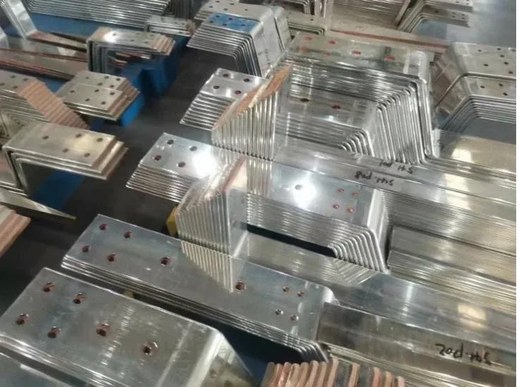
A busbar can pass a hole-position check and still damage its insulation during assembly. The problem may be a thin lip at the exit of a punched hole, a sharp sheared corner, or a particle left behind after finishing. None is reliably described by the instruction “make the part smooth.”
Good busbar deburring starts by identifying the defect and the surface that must be protected. It ends with a clean part that still meets its dimensional requirements. Removing more metal is not automatically an improvement, particularly around bolted contact faces.
The task here is edge control after cutting and forming. For the wider sequence of material receipt, machining, coating, and release, use the complete busbar fabrication workflow.
Trace the Burr Before Adding Another Finishing Pass
Map where the defect appears. A consistent burr on the punch exit side suggests a different investigation from a random scratch on a contact face. A worsening burr over a run can indicate tool wear or a changing process condition; a sudden one-sided defect warrants checking alignment and support.
Keep representative unprocessed and finished samples. Comparing them shows whether the finishing operation removed the original defect or merely folded it against the surface. A folded burr may look less prominent while remaining attached and vulnerable to breaking off later.
Upstream control matters. Wilson Tool’s busbar tooling information treats the punch-and-die system as a dedicated busbar application. In practice, the tool maker should confirm the appropriate configuration for the material, thickness, and hole. Do not compensate for an unsuitable or damaged tool by accepting an ever-longer abrasive cycle.
Record the defect location, affected tool station, material batch, and production count. This creates a useful maintenance signal and separates tooling problems from handling damage introduced after machining.
Specify an Edge Condition That Can Be Inspected
“Burr removed,” “edge broken,” “chamfered,” and “radiused” are not identical requirements. Burr removal addresses unwanted raised material. A chamfer or radius defines an intentional geometry. Surface roughness and particulate cleanliness are additional characteristics.
The drawing or control plan should identify which edges matter and how they will be checked. A hole used for a fastener may need a different edge treatment from an exposed corner under heat-shrink insulation. The contact land around that hole also needs protection from excessive finishing.
Useful instructions state the relevant maximum burr condition, permitted material removal, edge geometry where required, and inspection method. Where a numerical value cannot be justified yet, qualify the requirement with engineering and establish controlled acceptance samples. Do not invent a universal radius and label it an IEC requirement.
A photograph is helpful for locating an edge but rarely sufficient to prove its profile. Lighting, scale, and viewing direction can hide a small lip. Use appropriate magnification and profile measurement when the acceptance criterion requires them.
Choose the Process Around Access and Geometry
The appropriate method depends on whether the part is flat or formed, whether internal features are accessible, and how much stock may be removed.
| Method | Where it can be useful | Main control concern |
|---|---|---|
| Hand tools | Low-volume parts and accessible local edges | Operator variation, gouging, missed features |
| Abrasive brushing | Repeated accessible edges and light burrs | Tool wear, coverage, abrasive residue |
| Belt finishing | Flat parts with a suitable controlled route | Uneven stock removal and contact-face alteration |
| Machined edge treatment | A defined chamfer or radius | Setup, datum control, and access |
| Batch finishing | Qualified groups of compatible parts | Part-to-part damage, inaccessible edges, retained media |
An automated machine does not make every part suitable for the same recipe. The Valgro busbar finishing system is an example of equipment dedicated to copper and aluminum edge finishing. Its application description supports considering a dedicated process; it does not establish a universal acceptance result for an untested part.
Try the most difficult feature in the production family. Check narrow slots, holes near bends, short legs, and areas that the fixture shields. Confirm how the part will be held without damaging a finished contact surface.
Keep Contact Faces and Insulation Zones Separate
A bright surface is not necessarily a good electrical interface. Aggressive finishing can round the edge of a contact pad, create an uneven land, or remove plating. The joint may then assemble differently even though the part looks cleaner.
Define protected surfaces on the process drawing. Specify where masking, non-marking supports, or a separate operation is necessary. If a pre-plated bar is cut or bent, document the permitted coating condition at the worked edges and the approved response to exposed substrate.
Insulation areas present a different concern. Sharp projections and retained particles can damage a sleeve or interfere with a coating. Coordinate the edge requirement with the actual busbar insulation method; a sleeve application and a rigid coating need not have identical handling and preparation steps.
Cleaning belongs in the same route. Select a compatible method that removes the process residue without introducing moisture, chemicals, or particles that create a new problem. Drying, storage, and transfer to the next operation should be defined rather than left to workshop habit.
Qualify the Finished Part, Including Cleanliness
Acceptance should answer three questions: has the unwanted edge been removed, is the intended geometry still within tolerance, and is the part clean enough for its next operation?
For the trial batch, inspect both sides of holes and the full edge path. Measure critical dimensions again after finishing. Where the process can affect contact areas, check the specified flatness or profile rather than relying on overall thickness alone.
Include an inspection for retained abrasive, chips, and loose material using the agreed method. If the customer specifies a particulate cleanliness test, define its sampling and reporting requirements before quotation. A visual check should not be presented as equivalent to a quantitative extraction test.
Record tool condition and process settings with the accepted samples. Repeat the checks after the planned tool-change interval and after any material or geometry change. The copper busbar inspection checklist can carry these controls into final release without duplicating every upstream measurement.
Feed Defects Back Into Punching and Shearing
Finishing time is a useful production measure, but track it alongside the defect rate and accepted-part yield. A shorter cycle that sends damaged insulation surfaces downstream is not a saving. A longer cycle caused by progressive tool wear is a reason to inspect the cutting process.
For a DHCNC-BP-60 punching and shearing workstation, include representative edge quality in the part trial and acceptance agreement. Do not replace that evidence with a promise that all output will be “burr-free.” The result depends on the stock, tooling, setup, and the defined edge requirement.
The practical goal is a stable process: predictable edges from cutting, controlled removal where needed, protected functional surfaces, and an inspection method that catches deterioration before it becomes a batch of damaged parts.
Frequently Asked Questions (FAQs)
Is a finger check enough to accept a deburred busbar?
No. Bare-hand checks can cause injury and do not establish a measured edge condition. Use the inspection method, magnification, gauges, and acceptance samples specified in the control plan.
Should busbars be deburred before or after plating?
Major edge finishing is normally planned before plating so the finished edge can receive the intended coating. Any finishing of pre-plated material or post-plating rework needs an approved route that addresses exposed substrate and coating damage.
Can rounding an edge make the part nonconforming?
Yes. Excessive material removal can alter hole geometry, contact area, thickness, or a controlled edge profile. An edge that feels smooth can still be outside the drawing requirements.
Why does a hole still have a burr after the flat faces are brushed?
The brush may not reach the hole entrance or exit effectively. Inspect the internal edge separately and use a qualified tool or process suitable for that feature.
DHCNC-BP-60 CNC Punching & Shearing Workstation
Discover details, parameters, standard dies packages, and factory quotes.