
AI Rack Busbar Prototypes: From OCP 2026 Designs to Production
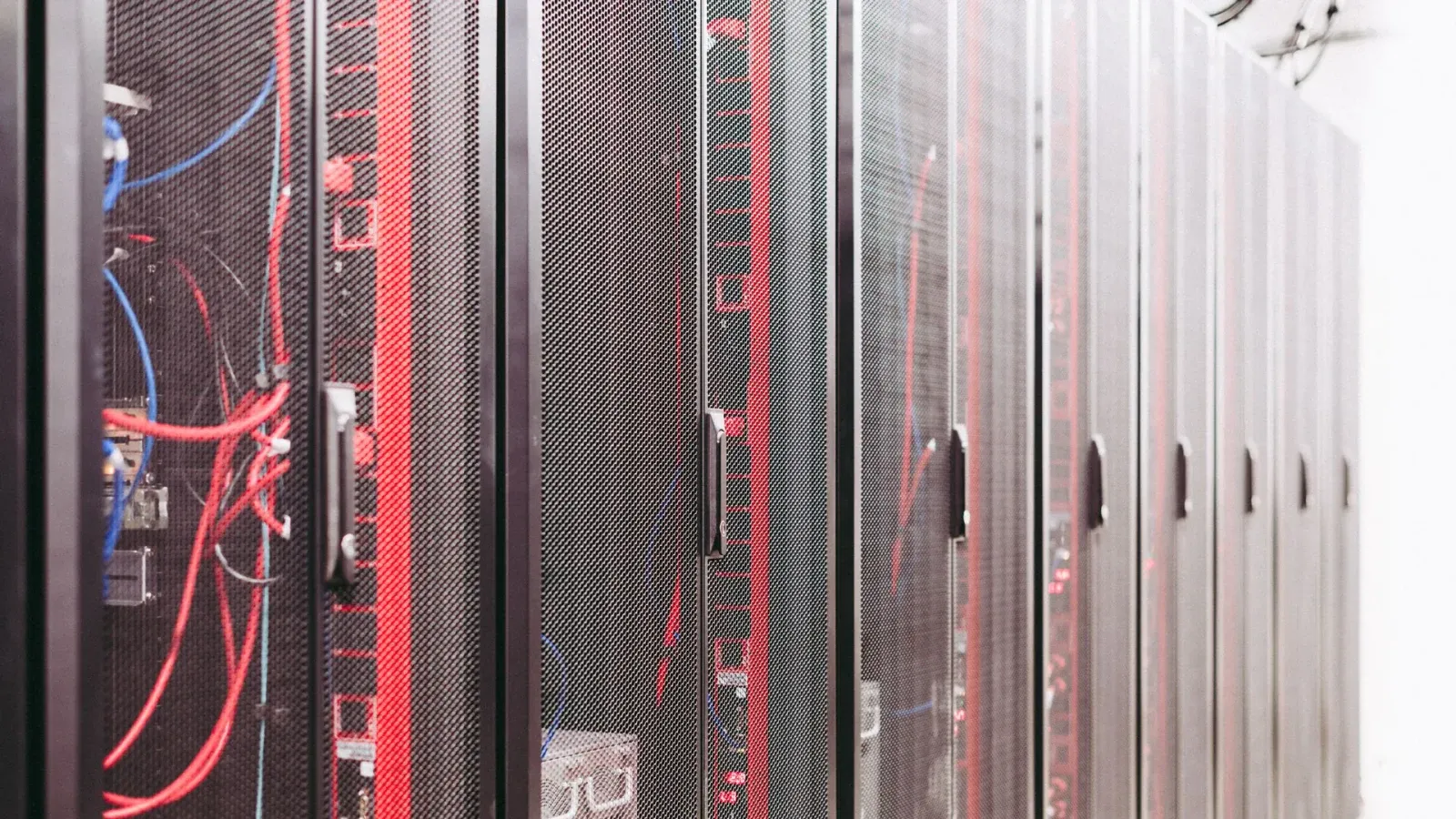
An AI rack busbar prototype often arrives with a settled conductor length and an unsettled connector footprint. The shop can quote the flat part, but the hole pattern that controls the tooling is still moving. That is the point to separate a prototype quotation from a production release.
The October 2026 OCP announcements make the distinction urgent. On October 12, NVIDIA contributed its Vera Rubin rack and compute-tray designs to OCP through MGX and described an MGX 1.2 specification with rack-scale blind-mate liquid cooling, a liquid-cooled 5,000 A busbar, native 19-inch equipment support and rack deployments up to 250 kW. NVIDIA also described Visionbay’s planned K-1 platform around 800 VDC. The current rating and voltage belong to different items; they do not define a universal “5,000 A, 800 VDC” rack busbar specification.
For a fabricator moving an AI rack busbar prototype to production, the next step is to identify the actual component being ordered and the interfaces that are ready to manufacture. An OCP contribution is an architecture document, not a controlled part drawing.
Start with the supplied part, not the rack rating
A rack-level busbar may sit behind a blind-mate connector, carry a specific current and fit inside a defined rack envelope. The purchase order may cover the conductor only, a plated part, a laminated assembly, a flexible connection or a complete cooled assembly. Each requires a different production route. Establish which item the purchase order covers, who supplies the mating parts and who accepts the finished assembly.
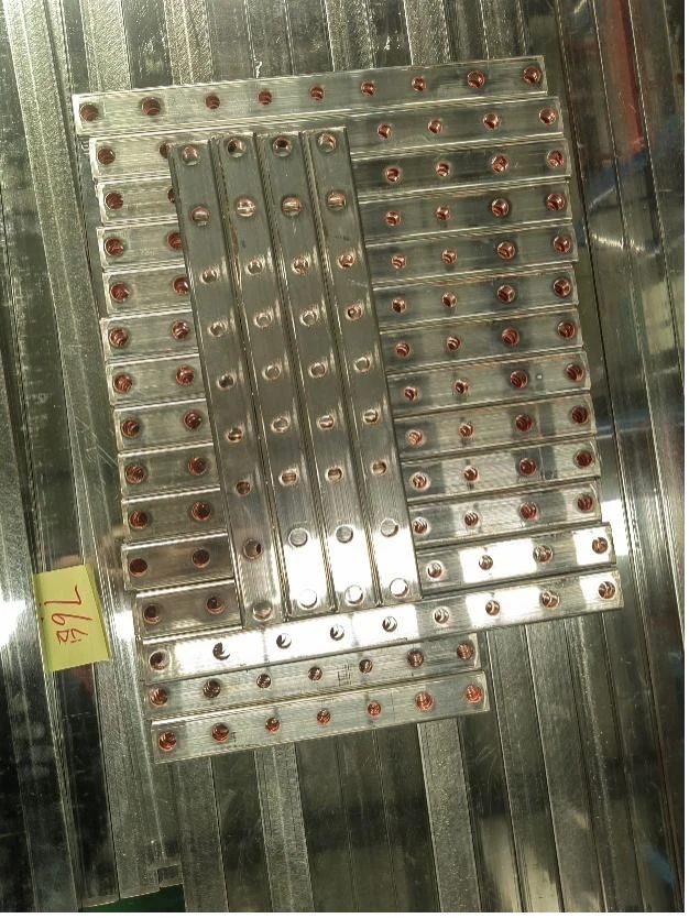
Start with inspectable features: hole locations, contact footprints, bend positions and the envelope available for the part. The straight busbar samples shown here illustrate general hole-pattern fabrication. A rack-specific sample needs its own material, section, dimensions and controlled drawing.
Punching, shearing and bending can address compatible conductor geometry. Cooling passages, joints, sealing, insulation and assembly verification require their own processes. Keep those operations in the scope even when a subcontractor performs them. The 800 VDC architecture guide covers the wider distribution context; the sample order must define the narrower manufacturing task. Everything below concerns the conductor-forming scope; a cooling loop, a sealed joint or an electrical connection needs its own qualification.
Freeze the interfaces that determine tooling
Rack busbar revision control needs more than a drawing filename. A connector footprint or mounting hole can change without altering the overall conductor length or the rack’s headline power rating. In an MGX-style rack, the blind-mate connector and rack envelope add another moving interface. Any of those changes may affect tooling already on order.
Maintain a short interface record with the sample package:
| Interface | Information needed for release | Consequence of a change |
|---|---|---|
| Electrical connection | Mating-part revision, contact footprint and orientation | Recheck contact-area geometry and hole pattern |
| Rack mounting | Datums, mounting locations and available envelope | Recheck locating features, bends and fit |
| Material and finish | Grade, condition and finishing specification | Reassess the manufacturing and finishing route |
| Nearby cooling hardware | Controlled clearance and mounting geometry | Recheck fit, tool access and assembly sequence |
| Acceptance | Inspection characteristics and design-owner approval | Update the sample evidence required for release |
Identify provisional dimensions explicitly. For example, if the connector footprint remains open but the material section is agreed, a general forming trial may be useful while a dedicated hole-pattern tool remains premature. The drawing owner should identify which decision the trial can support.
The busbar drawing and datum guide helps translate fit requirements into measurable features. Copying another project’s tolerances can add cost without resolving the interface that matters.
Give each sample a defined purpose
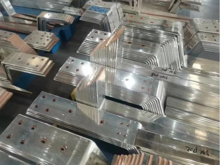
A fit sample answers a geometry question. It may use a different material or finish, provided those departures are recorded and it cannot be mistaken for an electrically qualified part. Check the intended connection and mounting arrangement against the controlled mating components. Measure the hole pattern against the mating connector, not only against the drawing.
A manufacturing sample uses the planned material and route to expose tool access, bend sequence, handling and inspection problems. Keep the material lot, program revision and tooling configuration with its inspection results. If the route changes later, determine which checks need to be repeated.
A pilot batch tests whether that route can be repeated with normal identification, inspection and handling. It also reveals whether parts that fail a check can be separated and traced. Electrical, thermal and cooling-system qualification remain with the organizations responsible for those requirements.
Sample acceptance and permission to ship production quantities are separate decisions. Record which drawing revision, quantity and delivery release each approval covers.
Quote reusable capability and dedicated tools separately
Ask your equipment supplier to split the quotation into reusable machine capability, standard tools and geometry-specific tools. For every dedicated tool, list the part revisions it serves and the work needed if an open interface changes. For a rack busbar, the dedicated tool may be a hole-pattern die or a bend tool; the reusable capability is the machine’s throat, stroke, control and standard tooling.
A DHCNC-BP-60 punching and shearing workstation can be assessed for the compatible flat-conductor operations in that route. Rack voltage and current alone cannot establish its suitability: use the actual material section, feature geometry and acceptance drawing.
Before releasing production tooling, assemble the controlled drawings, accepted sample findings, pilot quantities, delivery schedule and remaining open interfaces into one release file. Watch for repeat orders on the same part family; that is the signal that a dedicated tool has a production life beyond the prototype. If the customer cannot name the drawing revision and the interface owner, what exactly is the sample proving?
Frequently Asked Questions (FAQs)
Does an open rack architecture provide a complete busbar production drawing?
Not necessarily. The buyer must identify the applicable specification revision and obtain the project-specific part, interface and acceptance documents. An architecture announcement is not a manufacturing release.
Can ordinary punching and bending equipment produce a complete liquid-cooled busbar assembly?
Punching and bending address only the compatible conductor-forming operations. Cooling passages, joints, sealing, insulation and assembly verification require their own processes and evidence; they are not established by a machine's forming capability.
When should prototype tooling become production tooling?
Release production tooling after the responsible design owner has accepted the relevant interfaces and the pilot route has demonstrated the required parts. Record remaining changes explicitly before committing to geometry-specific tooling.
What did MGX 1.2 add that matters to a busbar fabricator?
The specification adds rack-scale blind-mate liquid cooling, a liquid-cooled 5,000 A busbar, native 19-inch equipment support and rack deployments up to 250 kW. Those are architecture-level features. The fabricator still needs the controlled part drawing, mating interface and acceptance criteria for the specific busbar.
DHCNC-BP-60 CNC Punching & Shearing Workstation
Discover details, parameters, standard dies packages, and factory quotes.