
Busbar Contact Resistance: Joint Design, Torque, Plating, and Test Methods
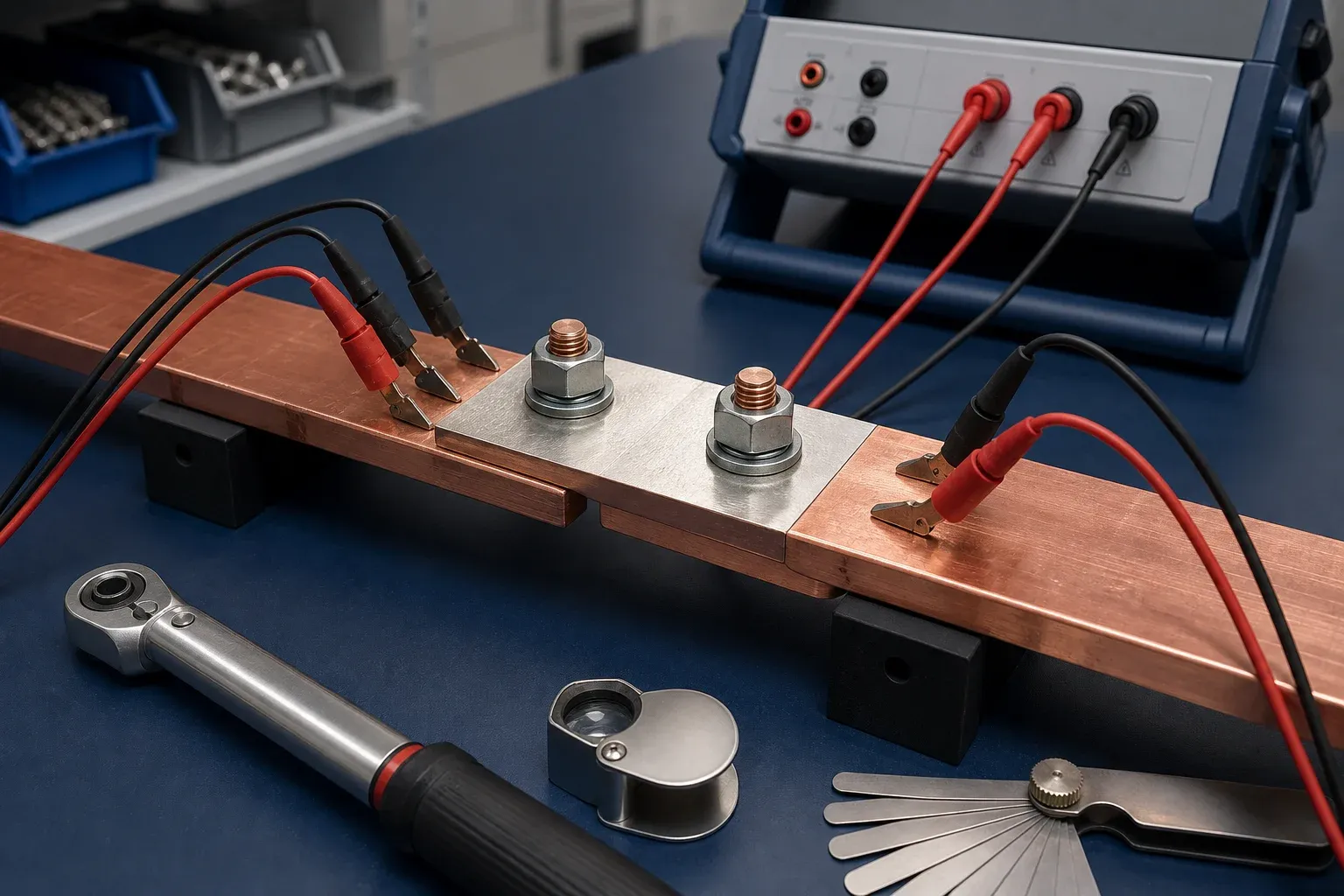
A bolted copper joint does not conduct across its entire visible overlap. At microscopic scale, current passes through a limited population of contact spots where surface asperities meet under pressure. Films, oxides, contamination, plating, flatness, and clamping-force distribution determine how many effective paths exist.
That is why a torque number alone cannot prove joint quality, and why a micro-ohm result copied from another design is not a valid acceptance limit. A defensible joint control plan connects geometry, surface process, assembly, measurement, and temperature performance.
Why the Joint Has More Resistance Than the Bulk Conductor
Even a polished surface is rough at microscopic scale. The real conducting area is smaller than the apparent overlap, so current constricts as it passes through contact spots. Surface films can add resistance, while higher stable contact pressure can increase the number and area of conductive spots.
The bulk resistance of the bars also contributes to any measurement taken some distance from the joint. Lead placement therefore changes the reported value. Define whether the test includes only the interface, the overlap plus adjacent conductor, or a larger assembly section.
COMSOL’s explanation of electrical contact resistance at bolted joints illustrates the coupled electrical-mechanical nature of the interface. A model remains dependent on its contact-pressure and material assumptions.
Begin With Geometry and Pressure Distribution
Joint overlap, conductor thickness, bolt number and spacing, washer or clamping hardware, edge distance, hole clearance, and bar flatness affect pressure distribution. Adding a bolt does not automatically improve the result if the bars rock, the hardware bottoms, or one area carries most of the load.
The drawing should define:
- conductor material, thickness, and contact dimensions;
- hole or slot size and position;
- required surface condition and finish;
- hardware specification and permitted reuse;
- assembly orientation and access;
- tightening sequence and project-controlled torque or tension method;
- any joint compound or lubricant specifically qualified for the design;
- inspection and test boundary.
Finite-element analysis or pressure-sensitive development methods can help with unusual joints, but production needs measurable characteristics and a repeatable procedure.
Surface Preparation and Plating Change the Interface
Bare copper, tin, and silver surfaces do not behave identically under heat, oxidation, storage, and assembly. Cleaning a plated surface with an abrasive method intended for bare metal may damage the coating. Applying an unapproved compound can change friction, contact behavior, or ageing.
Use the qualified finish process and handling instructions. Protect contact surfaces after fabrication, and inspect them immediately before assembly for contamination, deep scratches, coating loss, or foreign material. The busbar surface-treatment guide provides the material-selection context; it does not set the final joint resistance.
Published experiments can be useful only when their conditions are retained. An IEEE research record on busbar contact resistance may inform the mechanism, but its materials, geometry, loads, and measurement method must be checked before applying a numeric result.
Hole Position, Burrs, and Bend Distortion Matter
Misaligned holes tempt assemblers to lever bars into place or force bolts through at an angle. The resulting preload can lift one edge of the contact surface. A bend located too close to the joint may also distort the terminal plane, while a burr can prevent seating or damage plating.
Inspect terminal flatness and hole relationships on the finished formed part. A controlled punching and shearing process supports repeatability, but the joint result still depends on downstream bending, finishing, assembly, and testing.
Torque Is an Input, Not a Resistance Measurement
Torque creates bolt tension indirectly. The relationship is affected by thread and under-head friction, hardware condition, lubrication, plating, tool accuracy, tightening speed, and joint relaxation. Two nominally identical torque applications can therefore create different clamping forces.
Use the hardware and procedure specified by the design authority. Calibrate or verify the torque tool as required, follow the tightening sequence, and record the result. Replacing fasteners, adding lubricant, changing washers, or retightening after service should follow an approved procedure rather than workshop habit.
Do not increase torque simply because resistance is high. First confirm the measurement setup, then inspect geometry, surface condition, hardware, and assembly. Over-torque can create a new defect.
Plan a Four-Wire Micro-Ohm Measurement
In a four-wire or Kelvin method, one pair of leads supplies test current and another pair senses voltage. Separating those functions reduces the influence of test-lead and clamp resistance.
A usable procedure defines:
- instrument identity, verification, and suitable range;
- the joint’s condition and temperature;
- test current and stabilization period;
- current-lead positions outside the voltage-sense points;
- voltage-lead positions that define the measured boundary;
- surface contact method for the probes;
- repeat, reverse-polarity, or consistency checks where applicable;
- calculation, temperature notation, and reporting units;
- acceptance source and action for an abnormal result.
Measure equivalent joints with equivalent lead positions. A comparison loses value if the sense points move or one result includes more bulk conductor.
Set Acceptance From the Design and Test Plan
There is no sound universal answer to “How many micro-ohms should a busbar joint have?” A larger joint, different material, longer measurement span, or different test current produces a different result.
Acceptance can be based on an approved design calculation, qualified reference joint, type or design verification, specified temperature performance, and statistically controlled production baseline. State whether the value is an absolute limit, a comparison to a reference, or a trend trigger.
| Decision input | Why it is needed |
|---|---|
| Joint drawing and materials | defines the physical interface |
| Test boundary and method | makes results comparable |
| Reference or verification basis | connects resistance to proven performance |
| Temperature condition | resistance changes with temperature |
| Instrument capability | establishes credible resolution and uncertainty |
| Disposition rule | prevents ad hoc retorque or unapproved rework |
For IEC switchgear context, use the project’s assembly verification framework rather than treating a micro-ohm check as a substitute for temperature-rise or short-circuit verification.
For installed energized equipment, infrared inspection can screen a joint before a shutdown, but bare copper emissivity and operating load can distort the apparent result. The 2026 busbar thermography workflow shows how to record comparable conditions and turn a thermal pattern into an investigation rather than an assumed diagnosis.
Diagnose High Resistance Systematically
| Finding | Check next | Avoid |
|---|---|---|
| One inconsistent reading | probe contact, lead location, instrument range | reworking the joint before confirming the test |
| High result repeated on one joint | flatness, contamination, hardware, torque record | blindly adding torque |
| High results across a batch | finish lot, material, assembly tools, process change | treating every part as an isolated defect |
| Resistance rises after cycling | relaxation, thermal movement, plating, pressure distribution | using the initial result as lifetime proof |
| Acceptable resistance but hot joint | current distribution, cooling, sensor location, adjacent sources | assuming the electrical test covers system thermal behavior |
Joint resistance belongs inside the broader switchgear busbar manufacturing process. Design the interface, manufacture the terminal accurately, assemble it under a controlled procedure, and test it against an explicit boundary.
Frequently Asked Questions (FAQs)
What is an acceptable contact resistance for a busbar joint?
There is no universal micro-ohm value for every busbar joint. Acceptance must be derived from the joint design, material, plating, geometry, hardware, temperature-rise and verification basis, test method, and an agreed reference or project specification.
How is busbar contact resistance measured?
A four-wire Kelvin method is commonly used so test current and voltage-sensing leads are separated. The procedure must define current, lead positions, temperature, surface state, instrument verification, settling, polarity or repeat readings, and the exact boundary included in the result.
Does higher bolt torque always reduce joint resistance?
No. Torque is an indirect way to create clamping force and is affected by friction, hardware, lubrication, sequence, and tool condition. Excess torque can damage threads, hardware, or the conductor without producing a sound pressure distribution.
How do tin and silver plating affect a bolted busbar joint?
Plating changes the contact-surface chemistry and behavior, but its effect depends on the complete joint, coating thickness and condition, assembly process, temperature, and environment. Use a qualified finish and do not mix preparation practices without review.
Can misaligned holes increase busbar joint resistance?
They can contribute by forcing the bars out of plane, reducing usable overlap, or creating uneven pressure. Hole alignment is not the only variable, so a high result should be diagnosed across geometry, surfaces, hardware, assembly, and measurement setup.
DHCNC-BP-60 CNC Punching & Shearing Workstation
Discover details, parameters, standard dies packages, and factory quotes.