
CNC Busbar Machine Accuracy: How to Test Positioning and Repeatability
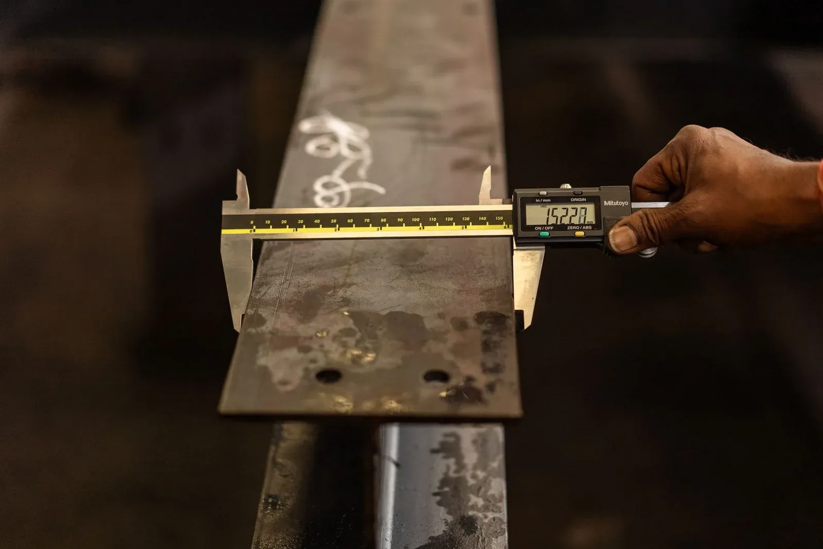
A CNC busbar machine is not accurate merely because one finished part matches a drawing. That result combines the machine, tooling, program, material, operator, measurement method, and sometimes selective adjustment. A useful acceptance test separates those contributors and asks whether the purchased process can produce the required features repeatedly across the intended work range.
The buyer should therefore replace a quotation line such as “positioning accuracy: ±0.2 mm” with an acceptance matrix. The matrix identifies the characteristic, datum, test locations, repetitions, instrument, calculation, acceptance rule, and remedy. This makes supplier offers comparable and gives both parties a defensible baseline for factory acceptance and site acceptance.
Accuracy, Repeatability, and Part Capability Are Different Claims
Accuracy describes agreement with a specified or reference value. Repeatability describes the spread of repeated results under stated conditions. They answer different questions. Five holes can form a tight cluster and still be displaced from their commanded position; that process is repeatable but biased. A group centered on the nominal position but widely scattered is not repeatable enough for production.
Axis performance is narrower than finished-part capability. The ISO 230-2 test-code page identifies methods for determining the accuracy and repeatability of positioning of numerically controlled axes. A machine-tool study also illustrates why direction of approach, measurement locations, repeated runs, and statistical evaluation matter when characterizing positioning error in a structured accuracy and repeatability test.
A punched busbar trial is valuable, but it is not automatically a complete ISO 230-2 test. It adds feeder grip, tool clearance, material movement, burr, part measurement, and other process effects. State clearly whether the contract requires an axis test, a finished-part capability test, or both.
Translate the Drawing Into an Acceptance Matrix
Start with the features that determine assembly, not the easiest features to measure. A representative matrix might include:
| Characteristic | Functional reference | Main contributors | Suitable evidence |
|---|---|---|---|
| Hole-to-hole pitch | drawing datum system | axis positioning, feed grip, punch clearance | repeated coordinate measurements |
| Hole to sheared end | finished end or specified datum | positioning plus shear sequence | measured samples across bar lengths |
| Slot orientation | primary edge and hole pattern | tool orientation, program, material restraint | first article and repeat samples |
| Bend angle | agreed leg surfaces | stroke, tooling, material springback | controlled material lot and angle method |
| Terminal-plane offset | final assembly datums | accumulated hole, length, and bend variation | fixture or coordinate measurement |
Do not assign an arbitrary tolerance simply because a machine brochure publishes one number. The part drawing should define the functional requirement. The machine test then demonstrates whether the process has enough margin to meet it. The finished-busbar inspection checklist provides a broader view of material, geometry, contact faces, coating, and records that remain outside a positioning test.
Record the exact drawing revision and program used. If the supplier changes a datum, edits the program between samples without recording the change, or measures from a different edge, the dataset no longer represents one controlled test.
Test Punching and Positioning Without Cherry-Picking a Part
Warm the machine according to the agreed operating procedure before collecting acceptance data. Then exercise short and long moves at several useful positions in the travel rather than making every hole near one convenient point. Where the mechanism can approach a coordinate from two directions, include both directions so reversal effects are not hidden.
Use enough repeated cycles to show a distribution, not a showcase sample. The buyer and supplier should agree in advance whether results are reported as individual deviations, range, mean and standard deviation, or another defined statistic. Retain every reading, including failed or interrupted runs, with an explanation of any exclusion.
For a punching and shearing workstation, use stable material that the clamps can hold consistently. Inspect burr and distortion separately; a hole center can be correct while worn tooling produces an unacceptable edge. The DHCNC-BP-60 product page describes the model’s processing role, but a purchase contract still needs to connect any published machine specification to the buyer’s actual part, tooling, and measurement plan.
Long parts deserve special attention because feed and datum errors can accumulate or appear only after repositioning. Include the buyer’s difficult hole-to-hole span and a realistic end cut rather than testing a small coupon alone.
Separate Bending-Axis Performance From Copper Process Variation
Bending acceptance is a process test. The controller may return to the same commanded stroke while finished angles change because copper thickness, temper, rolling condition, tool radius, lubrication, or part temperature changed. The result can also shift when the operator measures a short leg at a different contact point.
Control one material lot and record its specification and measured thickness. Fix the tool set, orientation, program revision, bend sequence, and measurement method. Measure after the same relaxation interval and at the same surfaces. If production must cover multiple grades or thicknesses, run separate capability sets instead of combining them into one misleading average.
Angle alone may not protect assembly. An offset part can have two acceptable individual angles but the wrong terminal-plane separation. Use the final datums from the drawing and follow the flat-pattern controls described in the busbar bend allowance and K-factor guide.
Control Measurement Uncertainty Before Comparing Results
An acceptance tolerance close to the resolution or uncertainty of the measuring system produces arguments rather than evidence. Identify the instrument, calibration status, resolution, fixture, operator method, and environmental conditions. Confirm that a caliper is suitable for the feature; hole position relative to a datum may require a fixture, vision system, height gauge, or coordinate measurement.
Run a short measurement-system exercise before testing the machine. Have the same operator repeat selected measurements, then compare operators if more than one person will inspect. Large measurement variation must be corrected before it is attributed to the machine.
The supplier’s and buyer’s instruments also need correlation. Measuring the same retained reference part at the factory and after installation can expose a method difference before SAT. Photographs of the setup are useful, but raw readings and fixture definitions are what make the result reproducible.
Write the Evidence and Remedy Into the Purchase Contract
The acceptance appendix should state who supplies material and tooling, who operates the machine, who measures, how data are calculated, and what happens after a nonconformance. Remedies might include adjustment and one controlled retest, replacement of an out-of-scope tool, or another response tied to the cause. Avoid an unlimited cycle of tuning until one part passes.
The broader CNC busbar machine FAT/SAT protocol should reference this accuracy matrix alongside safety, documentation, throughput, changeover, and service checks. At SAT, repeat an agreed baseline after installation, leveling, electrical connection, and environmental stabilization. If freight or foundation conditions changed the result, the retained FAT data help isolate the change.
The goal is not the smallest number in a brochure. It is a measured, contractually defined process that produces the buyer’s functional features with adequate and demonstrable margin.
Frequently Asked Questions (FAQs)
What is the difference between busbar machine accuracy and repeatability?
Accuracy describes how closely a result agrees with the specified or reference value, while repeatability describes the spread when the same operation is repeated under stated conditions. A machine can repeat a consistent offset, so both characteristics must be tested.
Is one accurate busbar sample enough to accept a CNC machine?
No. One part can be selected, reworked, or produced at a favorable point in the machine's travel. Acceptance should use an agreed sample size, multiple axis positions, repeated cycles, controlled material, and retained raw measurements.
Why is busbar bending accuracy affected by the copper material?
The finished angle depends on more than axis position. Copper grade and temper, thickness, grain condition, tool radius, lubrication, temperature, and springback all contribute, so the test must control or record those variables.
Should SAT repeat the same accuracy test used during FAT?
SAT should repeat a practical baseline derived from the FAT with the installed machine, agreed material, tooling, program, instruments, and method. It may be shorter than the factory test, but its results should remain directly comparable.
DHCNC-BP-60 CNC Punching & Shearing Workstation
Discover details, parameters, standard dies packages, and factory quotes.