
Bending Force and Tonnage Calculations for Heavy Copper Busbar Plates
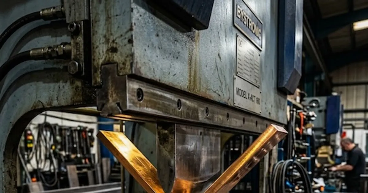
In industrial power distribution and switchgear manufacturing, forming thick copper busbars requires massive forces. When bending heavy copper plates—such as $100 \times 10 \text{ mm}$ or $120 \times 12 \text{ mm}$ profiles—understanding the mechanical requirements is critical.
Calculating the Bending Force (Tonnage) ensures that:
- The machinery is never overloaded, protecting hydraulic pumps and structural monoblock cast frames from fatigue.
- The V-die tooling is correctly specified to prevent premature cracking of the copper’s outer fibers.
- The spatial alignment remains locked, ensuring high angular repeatabilities under continuous operation.
For mid-to-high volume switchboard assembly, planning these forces is essential. This paper analyzes the formulas and practical calculations for air bending high-conductivity T2 copper plates using the DHAC-BB-H Dedicated Servo-Hydraulic Bending Machine or the bending station of our 3-in-1 multi-station busbar processor.
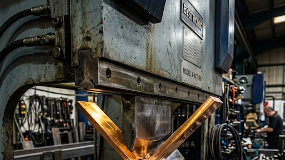
1. The Mathematical Bending Force Formula
For standard 90° air bending of sheet metal and heavy conductive bars, engineers utilize a classic beam-deflection formula modified by empirical coefficients.
The required Bending Force ($F$) is calculated as:
$$F = \frac{C \cdot \sigma_b \cdot W \cdot T^2}{1000 \cdot V}$$
Where:
- $F$ = Required Bending Force in Metric Tons (t).
- $C$ = Empirical shape/material coefficient (typically $1.5$ for standard copper air bending).
- $\sigma_b$ = Ultimate Tensile Strength of the material in $\text{N/mm}^2$ (or $\text{MPa}$). For standard half-hard T2 red copper, $\sigma_b \approx 260 \text{ MPa}$.
- $W$ = Width of the copper busbar in $\text{mm}$.
- $T$ = Thickness of the copper busbar in $\text{mm}$.
- $V$ = V-die opening width in $\text{mm}$ (typically chosen between $6T$ and $8T$ to prevent cracking).
Note: The division by 1,000 converts the output from kilonewtons ($\text{kN}$) into standard Metric Tons ($\text{t}$), which is the rating system for industrial hydraulic cylinders.
2. Practical Calculation Walkthroughs
To demonstrate how this formula operates in a real-world switchgear plant, let us calculate the required tonnage for two common B2B copper configurations:
Scenario A: Processing a $100 \times 10 \text{ mm}$ Copper Bar
- Material: Half-hard T2 Red Copper ($\sigma_b = 260 \text{ MPa}$)
- Width ($W$): $100 \text{ mm}$
- Thickness ($T$): $10 \text{ mm}$
- V-Die Opening ($V$): We select a standard $8T$ ratio, meaning $V = 8 \times 10 \text{ mm} = 80 \text{ mm}$.
Applying the formula:
$$F = \frac{1.5 \times 260 \times 100 \times 10^2}{1000 \times 80}$$
$$F = \frac{1.5 \times 260 \times 100 \times 100}{80000}$$
$$F = \frac{3,900,000}{80,000} = 48.75 \text{ Metric Tons}$$
Engineering Conclusion: To bend a $100 \times 10 \text{ mm}$ copper bar with a standard $V=80\text{mm}$ die, the hydraulic system must exert at least 48.75 Tons of press force. Our DHAC-BB-H Servo Bending Workstation provides a robust 50-to-80 Ton capacity, easily accommodating this load with a comfortable safety margin.
Scenario B: Processing a $120 \times 12 \text{ mm}$ Copper Bar (Heavy Busduct Specification)
- Material: Half-hard T2 Red Copper ($\sigma_b = 260 \text{ MPa}$)
- Width ($W$): $120 \text{ mm}$
- Thickness ($T$): $12 \text{ mm}$
- V-Die Opening ($V$): Using $V = 8T = 8 \times 12 \text{ mm} = 96 \text{ mm}$.
Applying the formula:
$$F = \frac{1.5 \times 260 \times 120 \times 12^2}{1000 \times 96}$$
$$F = \frac{1.5 \times 260 \times 120 \times 144}{96000}$$
$$F = \frac{6,739,200}{96,000} = 70.20 \text{ Metric Tons}$$
Engineering Conclusion: This heavy-duty application requires 70.2 Tons of force. Operating a standard manual 30-ton bender on this profile will lead to structural deflection, hydraulic line blowouts, and uneven bend geometries.
3. V-Die Selection & Tonnage Mapping Matrix
Choosing the correct V-die opening width is a delicate balance. A wider V-die reduces the required force but increases the minimum physical bend radius and requires a longer flat section at the ends of the bar.
The table below maps the required tonnage and minimum inner bend radii ($R_{\text{min}}$) for various material thicknesses ($T$) across a standard $100 \text{ mm}$ width of half-hard copper, assuming a standard $\sigma_b = 260 \text{ MPa}$:
| Thickness ($T$) | V-Die Width ($V$) | Target Ratio | Required Force (per 100mm width) | Minimum Inner Radius ($R_{\text{min}}$) | Sourcing Equipment Profile |
|---|---|---|---|---|---|
| 5 mm | 30 mm | 6T | 16.3 Tons | 3.5 mm | DH303-8P Multi-Station |
| 8 mm | 50 mm | 6.2T | 29.9 Tons | 6.0 mm | DH303-8P Multi-Station |
| 10 mm | 60 mm | 6T | 65.0 Tons | 8.0 mm | DHAC-BB-H Servo Bending |
| 10 mm | 80 mm | 8T | 48.7 Tons | 10.0 mm | DHAC-BB-H Servo Bending |
| 12 mm | 80 mm | 6.6T | 105.3 Tons | 12.0 mm | Dedicated High-Tonnage Custom |
| 12 mm | 96 mm | 8T | 87.7 Tons | 15.0 mm | DHAC-BB-H Servo Bending |
4. Engineering Safe-forming Protocols
To prevent mechanical damage and surface fractures during high-tonnage bending operations:
- Grain Direction: Whenever possible, bend the copper plate perpendicular to the rolling grain direction of the metal. Bending parallel to the grain reduces ductility and can trigger micro-cracks on the outer radius.
- Die Lubrication: Apply high-viscosity stamping oil to the V-die shoulders. This reduces friction, minimizing surface scoring on the copper plate and decreasing required force by up to 5%.
- Avoid Under-Sizing V-Dies: Never attempt to bend a 10mm copper plate on a 40mm V-die ($4T$). This raises the required force exponentially ($F \propto 1/V$) and can cause catastrophic cylinder failures.
5. Advanced Closed-Loop Hydraulic Bending
On conventional hydraulic press brakes, managing springback requires constant manual adjustments due to fluid viscosity changes as temperatures rise.
The DHAC-BB-H horizontal busbar bender resolves this through a closed-loop servo-hydraulic system. Real-time pressure sensors measure the resistive load curve during the initial stroke, allowing the Siemens PLC to calculate exact yield points and automatically adjust the cylinder’s over-travel depth. This ensures a consistent ±0.2° angular precision without operator intervention.
Switchgear procurement managers can request a custom tooling engineering evaluation to submit CAD drawings and receive a detailed calculations audit for their specific copper components.
Frequently Asked Questions (FAQs)
How does the V-die opening width affect the required bending force?
The required bending force is inversely proportional to the V-die width (V). Doubling the V-die width cuts the required tonnage in half, but it also increases the minimum physical bend radius and creates longer straight flat leg margins.
What is the standard yield strength parameter used for T2 copper in bending calculations?
For standard half-hard T2 copper (Y2), engineers use a tensile strength (Rm) of 250 to 300 MPa in the bending formula to ensure hydraulic systems are built with a safety buffer.
DHAC-BB-H Servo-Hydraulic Busbar Bender
Discover details, parameters, standard dies packages, and factory quotes.