
Hydraulic Busbar Bender Maintenance: A Condition-Based Schedule
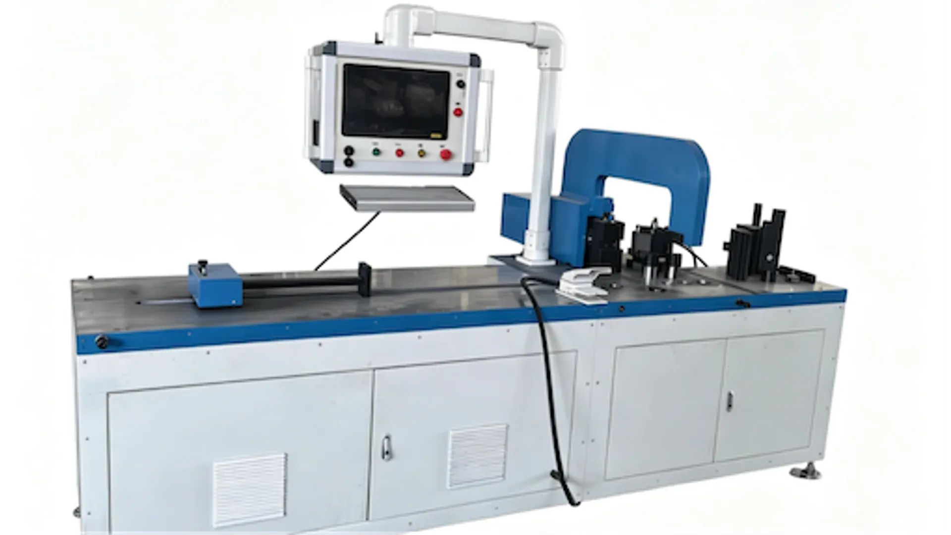
The useful life of a hydraulic busbar bender is not determined by how often someone wipes the frame or changes oil on a fixed anniversary. It is determined by whether the factory controls contamination, heat, leakage, alignment, stored energy, and the small changes that appear in finished bends before they become a breakdown.
A maintainable process has three layers: the machine manufacturer’s requirements, a measured health baseline, and inspection frequencies adjusted to duty and environment. A dusty plant running thick copper across two shifts should not copy the same calendar used by a clean, lightly loaded workshop. Nor should either plant extend a service interval simply because the machine still completes a cycle.
Start With an OEM Baseline, Not a Generic Calendar
Before creating checklists, assemble the controlled information for the installed machine:
- model, serial number, controller and software revision;
- hydraulic fluid specification and permitted alternatives;
- reservoir capacity, filter elements and breather details;
- normal pressure, temperature and cycle-time ranges under stated conditions;
- lubrication points and approved lubricants;
- hose, seal, valve, cylinder and tooling drawings;
- alarm history, parameter backup and electrical schematics;
- inspection, replacement and calibration requirements in the OEM manual.
The DHAC-BB-H bending-machine page identifies the equipment’s processing role. It does not replace the serial-specific manual or authorize a technician to alter hydraulic pressure, safety parameters, or controller settings. Put those controlled limits in the maintenance record and restrict changes to qualified personnel.
Use calendar tasks where aging is time-dependent, operating-hour tasks where wear follows use, and condition triggers where temperature, oil analysis, leakage, filter restriction, noise, or part quality gives better evidence. The result is still a schedule, but one that reacts to the machine rather than pretending all service lives are identical.
Make Energy Isolation the First Maintenance Step
Hydraulic maintenance can expose a technician to electrical supply, pressurized fluid, gravity, tooling, and stored mechanical energy. Turning off the HMI is not energy isolation. The U.S. Occupational Safety and Health Administration’s hazardous-energy overview explicitly includes hydraulic energy and describes the role of machine-specific lockout/tagout procedures during servicing.
The factory’s authorized procedure should identify every energy source, isolation point, verification step, blocking requirement, and person responsible. It should address residual pressure and any moving element that could descend or shift. Remote troubleshooting must never become permission to defeat an interlock or ask an operator to reach into a hazardous area.
Keep operational observations separate from tasks that require access. An operator may be authorized to check a sight gauge or external leak point while the machine is in its normal guarded condition. Opening a cabinet, breaking a hydraulic connection, entering a tooling area, or adjusting a sensor belongs under the applicable energy-control and safe-work procedure.
Capture a Daily Health Signature
A short observation made consistently is more valuable than an elaborate checklist that no one completes. At the start of a shift or defined production run, record the items that can reveal change without dismantling the machine:
| Observation | Record under stated condition | Escalate when |
|---|---|---|
| Fluid level and appearance | machine position, temperature and sight-gauge level | unexplained loss, foam, cloudiness or unexpected color |
| External leakage | location and whether seepage is growing | active spray, damaged hose, pooling or hot-surface exposure |
| Sound and motion | normal cycle and tool return | cavitation-like noise, chatter, hesitation or uncontrolled motion |
| Temperature | measurement point and production state | outside the OEM range or rising against the same workload |
| Cycle time | one controlled program and material condition | sustained drift beyond the plant’s baseline |
| Bend coupon | material lot, thickness, tool and program | angle, offset or surface result outside the control limit |
The coupon matters because a hydraulic symptom can first appear as a process symptom. It also prevents the opposite mistake: blaming the hydraulic system when a new copper lot, changed thickness, worn tool, or edited compensation value caused the bend shift. The machine-accuracy acceptance guide explains how controlled material and measurement keep those variables separable.
Do not “top up and forget” after a falling oil level. Record how much was added and find the loss path. A sealed system that repeatedly needs fluid has a condition to investigate.
Control Contamination Before Replacing Components
Fine clearances in pumps and valves make solid particles, water, and degraded fluid expensive. Parker’s handbook of hydraulic filtration explains how contamination monitoring and filtration protect hydraulic systems. The practical lesson is broader than installing a filter: new fluid, transfer containers, breathers, opened hoses, repair practices, and the reservoir environment all affect cleanliness.
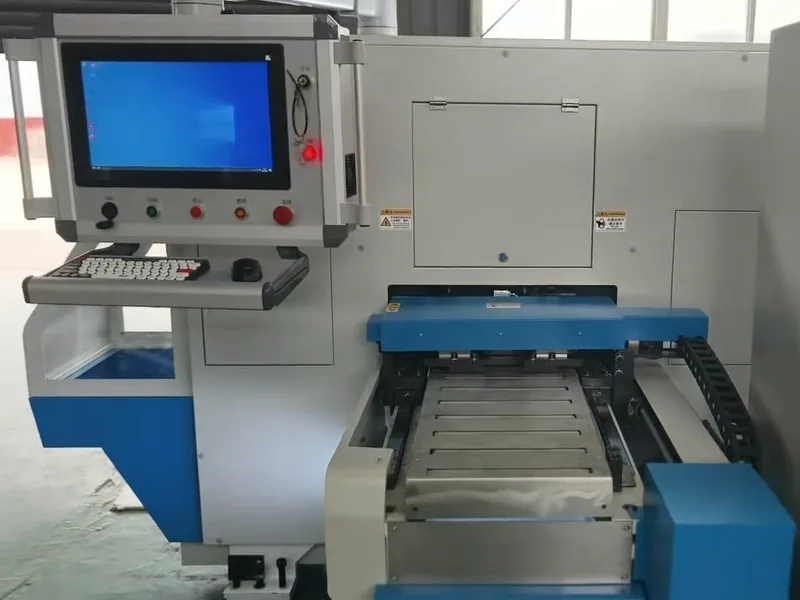
Define a clean-fluid handling route. Use sealed, identified containers and compatible transfer equipment. Keep filling points and tools clean. Replace a filter by condition indicator or approved interval, investigate an unexpectedly rapid restriction increase, and prevent dirt from entering while the housing is open. Do not assume new oil is clean enough for the installed components without the required handling and verification.
The target cleanliness code must come from the component and machine requirements. A generic article cannot select it for an unknown pump, valve block, feedback system, fluid, or operating pressure. Oil sampling also needs a consistent, representative point and procedure; a sample taken from a dirty drain pan says more about the pan than the circulating fluid.
Trend particle count, water, viscosity, oxidation or other properties selected with the fluid and laboratory supplier. A single report can identify a severe problem. A trend is better for deciding whether the fluid, filtration, operating temperature, or ingress control is changing.
Use Weekly and Monthly Measurements to Find Drift
The exact frequency belongs in the OEM-based plan, but the measured checks should cover the complete process rather than the reservoir alone.
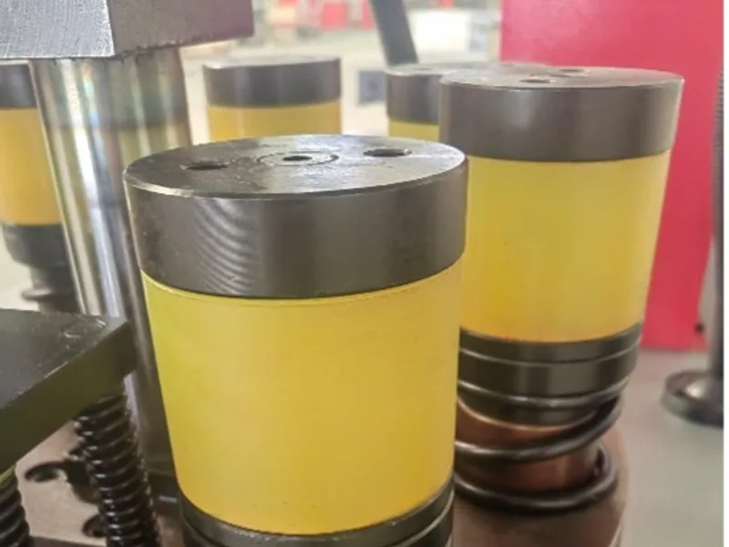
Inspect hoses for abrasion, blistering, cracking, incompatible routing and stressed fittings. Look for rubbed cables, loose connectors, blocked cooling airflow and damaged guards. Check tool seating, fasteners, backgauge or positioning references, and any surface that affects the final terminal plane. Verify safety functions only through the authorized test method.
Pressure is meaningful only with context. Record the test point, fluid temperature, command, tooling state, material or load condition, gauge identification and expected range. Increasing a relief or working-pressure setting to recover speed or force can conceal a worn component and overload another part; it is not a troubleshooting shortcut.
Combine the readings with production evidence:
- alarm and fault-code frequency;
- cycle-time distribution for a reference job;
- pressure and temperature under that job;
- leakage and make-up-fluid history;
- bend-coupon angle and final offset;
- unplanned stops and components replaced.
This dataset is also useful during the factory and site acceptance process. A baseline established at acceptance gives maintenance a defensible comparison instead of an operator’s memory of how the machine used to sound.
Escalate Symptoms With a Cause-and-Evidence Matrix
One symptom rarely proves one failed part. Use it to choose safe checks, not to order components at random.
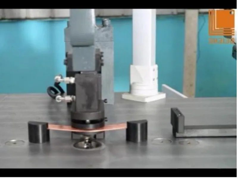
| Symptom | Plausible contributors | Evidence to collect before intervention |
|---|---|---|
| Slow or hesitant stroke | temperature, restriction, aeration, pump/valve wear, command issue | fluid temperature, pressure at defined points, filter status, noise, fault log |
| Rising oil temperature | cooling restriction, internal leakage, wrong viscosity, excessive pressure loss | ambient and oil temperatures, duty cycle, cooler condition, pressure data |
| Angle drift | copper lot/thickness, tool movement, thermal state, pressure/control drift | controlled coupon, material record, tool check, program revision, pressure/temperature |
| Repeated seal leakage | rod damage, contamination, misalignment, pressure spikes, seal incompatibility | leak location, rod surface, oil analysis, pressure history, installed part record |
| Cavitation-like noise or foam | low level, air ingress, suction restriction, return arrangement | level under correct condition, suction path, fluid appearance, recent service history |
Escalate with the evidence, serial number, operating state and recent changes. The service-response requirements in an after-sales support specification should define who can adjust parameters, expected remote-response information, spare-parts identification and when on-site support is required.
Prove the Machine Is Ready to Return to Production
Maintenance is not complete when the replacement part is installed. Close all opened connections correctly, account for tools and materials, reinstall guards, and confirm that leaks or contamination have not been introduced. Energy-control devices are removed only by the approved procedure and authorized people.
Perform the permitted no-load and functional checks, then repeat the controlled reference coupon with the same material, tool, program and measurement method used for the baseline. Inspect the first production part for the functional bend angle, terminal-plane offset, surface condition and any safety-critical feature. If the work involved controls, feedback, tooling alignment or pressure, expand the validation to match the risk.
Finally, record the symptom, cause, work performed, parts and fluid used, measurements before and after, parameter changes, validation results and approver. That history turns recurring maintenance into engineering evidence—and makes the next deviation much faster to diagnose.
Frequently Asked Questions (FAQs)
How often should hydraulic oil in a busbar bender be changed?
Use the machine and fluid suppliers' requirements together with oil analysis, contamination, temperature history, operating hours, and environment. A generic calendar interval can change usable oil too early or leave degraded oil in service too long.
What commonly causes a hydraulic busbar bender to lose angle consistency?
Possible contributors include material temper or thickness, tool movement, contaminated or aerated fluid, temperature-dependent behavior, pressure instability, valve or seal wear, feedback drift, and a changed program. A controlled bend coupon helps separate machine drift from material variation.
When should a hydraulic busbar machine be stopped instead of monitored?
Stop and follow the plant's safe shutdown and escalation procedure for a damaged hose, active high-pressure leak, abnormal pressure or temperature alarm, uncontrolled motion, failed guard or interlock, severe noise, smoke, or a safety-related fault. The OEM manual and risk assessment take priority.
How should a busbar bender be released after maintenance?
Close the work order, account for tools and guards, remove energy-control devices only under the approved procedure, inspect for leaks, run authorized no-load checks, make a controlled coupon, verify the critical dimensions, and approve the first production part.
DHAC-BB-H Servo-Hydraulic Busbar Bender
Discover details, parameters, standard dies packages, and factory quotes.