
Busbar Machine Tooling Packages: Specify Punches, Shears, and Bending Dies
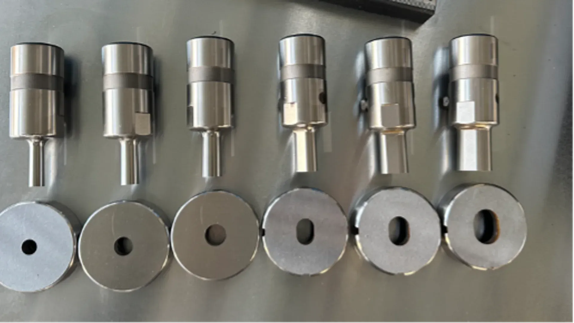
A busbar machine without the right tools is unused capacity. The machine may have adequate force and travel, yet fail to make the buyer’s recurring slot, short return bend or protected contact surface because the delivered package contains only generic demonstration tools.
The tooling specification should begin with released product features and end with verified sample parts. “Standard tool set included” is not a procurement description.
Build a Feature Inventory From Production Drawings
Export the feature requirements from a controlled sample of drawings. Consolidate identical features, but preserve material thickness, tolerance, datum relationship, finish condition and annual use. The resulting matrix might include:
| Feature family | Define | Typical purchasing output |
|---|---|---|
| round holes | diameter, material, thickness, location tolerance | identified punch-and-die pair |
| slots and obrounds | length, width, orientation and corner form | standard or custom matched pair |
| embosses and formed features | profile, direction, height and surface requirement | custom tool drawing and sample |
| straight shearing | material range, length and edge acceptance | blade scope and setting method |
| flat bends | angle, radius, leg, width and access | compatible punch/die combination |
| edge or vertical bends | orientation, section and nearby features | dedicated tool and sequence review |
| offsets and U-bends | gap, offset, internal clearance and return length | shaped tool set with access proof |
Rank each feature as high-frequency, boundary, customer-critical or occasional. This prevents the budget being consumed by rarely used tools while a daily production feature is omitted.
The CNC busbar machine selection guide helps confirm whether each operation belongs on the proposed machine. Tooling cannot add an unapproved process or extend a machine beyond its verified envelope.
Specify Matched Punch-and-Die Pairs
For each punching feature, state the punch geometry, mating die, holder, stripping arrangement and approved material range. Die clearance must be selected for the actual conductor and thickness, then validated against the required hole and edge condition. Avoid one universal clearance claim covering all materials.
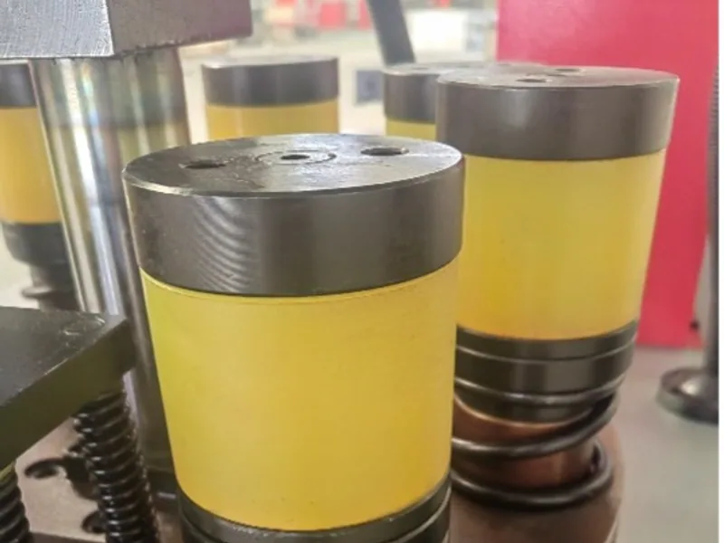
Ask the supplier to document:
- tool material and heat-treatment identification;
- nominal feature geometry and orientation;
- punch-to-die relationship and installed alignment method;
- compatible holders and station restrictions;
- lubricant or operating restrictions if any;
- sharpening allowance and minimum usable dimension;
- replacement and regrind route.
For a turret system, map every purchased tool to a station and check height or orientation constraints. The DHCNC-BP-60 punching and shearing workstation offers a seven-punch, one-emboss and one-shear working arrangement in its verified standard configuration; the buyer still needs a quotation-specific list of installed tools.
Wilson Tool’s busbar tooling overview is useful evidence that dedicated busbar punching solutions include round, shaped and forming applications. It does not establish tool life or acceptable quality for a particular copper grade, thickness or machine—those must be demonstrated.
Define Shear Output, Not Just Blade Supply
Specify required cut length, tolerance source, squareness where relevant, burr or rollover acceptance, deformation and surface condition. Identify the materials and thicknesses used for the test. Ask how blades are adjusted, reversed, sharpened and replaced, and which gauges or fixtures are needed.
If short remnants matter to nesting economics, define the operating condition and accepted remnant behavior in the machine specification. Do not infer it from a photograph of the shear. The tool register should include blade identifiers, drawing or dimensions, usable-edge policy and safe handling method.
Match Bending Tools to Radius, Orientation and Access
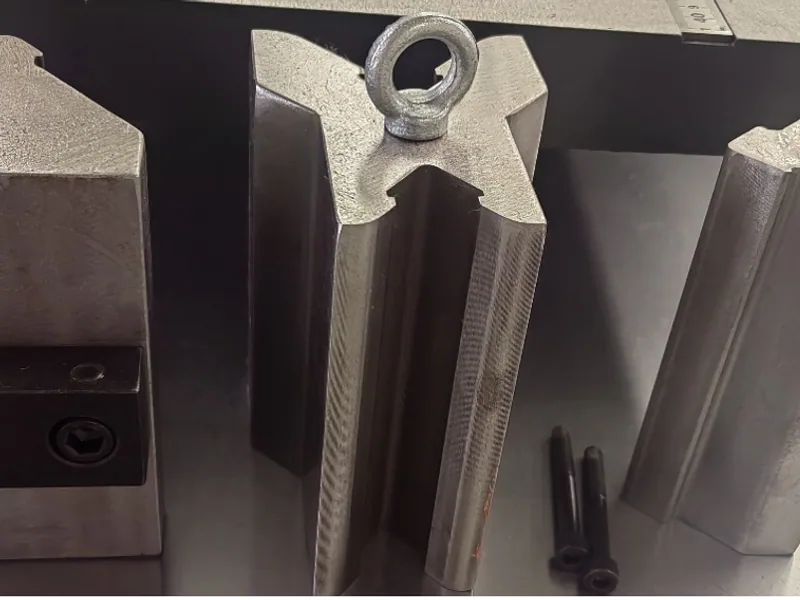
Bending tools need to make the required geometry without colliding with an earlier bend or marking a critical surface. For every bend family, specify:
- conductor section and condition;
- bend orientation and sequence;
- target angle and bend location;
- internal radius or functional fit requirement;
- minimum leg and return geometry;
- adjacent holes, insulation zones and contact faces;
- expected springback setup and verification method.
Use the busbar bending force and tonnage calculations to screen load and geometry, then require machine-and-tool confirmation. A calculation does not prove access or surface outcome.
For bend-focused work, the DHAC-BB-H bending center provides a verified equipment reference for flat and vertical capacity. The purchased die geometry, material condition and part sequence still define the usable application.
Protect Contact and Finished Surfaces
Identify plated, coated or electrically critical contact areas on the part drawing. Determine whether tool contact is permitted and what cosmetic or functional marking is acceptable. Options can include polished contact surfaces, replaceable protective interfaces, controlled film use or a different process sequence, but every option needs material and safety review.
Do not add soft material near a pinch or cutting zone without approval from the machine and tooling designers. A surface-protection method that can move, fragment or alter part location creates another risk.
Separate unavoidable process witness marks from damage. Photograph accepted reference surfaces under consistent lighting so receiving and production teams share the same standard.
Make Tools Traceable and Maintainable
Mark each tool or matched set with an identifier that connects to the register. Storage should prevent mixed pairs, corrosion, impact damage and uncontrolled access to heavy or sharp components.
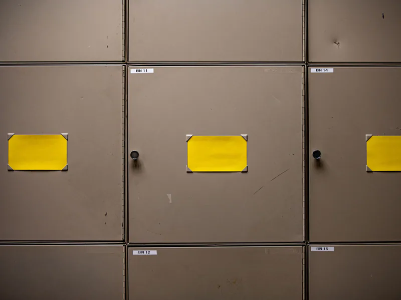
The tool record should contain:
| Record field | Purpose |
|---|---|
| unique tool ID and photograph | prevents mix-ups |
| feature and material range | controls application |
| holder/station compatibility | prevents setup error |
| baseline dimensions and sample | supports wear comparison |
| setup and compensation data | restores the accepted process |
| maintenance and wear limit | triggers planned action |
| supplier part number and drawing | enables replacement |
| reorder quantity and lead time | supports spare planning |
Do not publish a universal stroke-life promise in the purchase order. Tool life changes with material, alignment, clearance, lubrication, edge expectation and sharpening practice. Ask for stated conditions and establish the working replacement rule from inspected output and measured wear.
Distinguish Base, Production and Contingency Tooling
Structure the quotation in three layers:
- Machine-proving tools used for supplier checks and training.
- Production launch tools covering the released high-frequency and critical feature library.
- Contingency tools such as duplicate high-use punches, repairable assemblies or long-lead custom tools.
This prevents an apparently inexpensive base package from pushing essential tools into late options. It also avoids buying duplicates of low-use tools without a risk case. Coordinate the contingency layer with the CNC busbar machine spare-parts package.
Validate the Delivered Package With Parts
The tooling acceptance matrix should state the tool ID, machine station, material, sample drawing, characteristic, measuring method, pass/fail source and evidence file. Test frequent tools, custom tools and boundary tools; do not validate only one easy round hole.
For an integrated punching-and-shearing process, the tooling and process guide provides additional operating context. Keep procurement acceptance focused on the package actually purchased.
At handover, reconcile physical tools against the register, confirm holders and setup accessories, preserve accepted samples and backups, and identify every open item. The useful machine configuration is the machine plus the controlled tools that can reproduce the buyer’s parts.
Frequently Asked Questions (FAQs)
Which tooling should be included with a CNC busbar machine?
The included package should cover the buyer's released feature library and bend families, with identified punch-and-die pairs, shear tooling, bending tools, holders, setup data, storage, initial wear spares and custom-tool drawings where applicable.
Can one punch-and-die pair be used for every copper thickness?
Do not assume it can. Required die clearance and tool suitability depend on material, thickness, feature geometry, machine design and the accepted edge condition. The tooling supplier should document the approved operating range.
How should custom busbar tooling be accepted?
Run buyer-approved material and representative parts, measure the drawing characteristics and inspect edge, marking and surface condition. Retain the tool drawing, identifier, setup parameters, sample results and approved replacement reference.
What tooling data should be delivered with the machine?
Request a tool register with unique IDs, dimensions, compatible material range, holders, setup values, maintenance and wear criteria, drawings for custom tools, replacement part numbers, lead times and storage requirements.
DHCNC-BP-60 CNC Punching & Shearing Workstation
Discover details, parameters, standard dies packages, and factory quotes.