
Transformer Busbar Processing Machines: Specify a Heavy-Copper Workflow
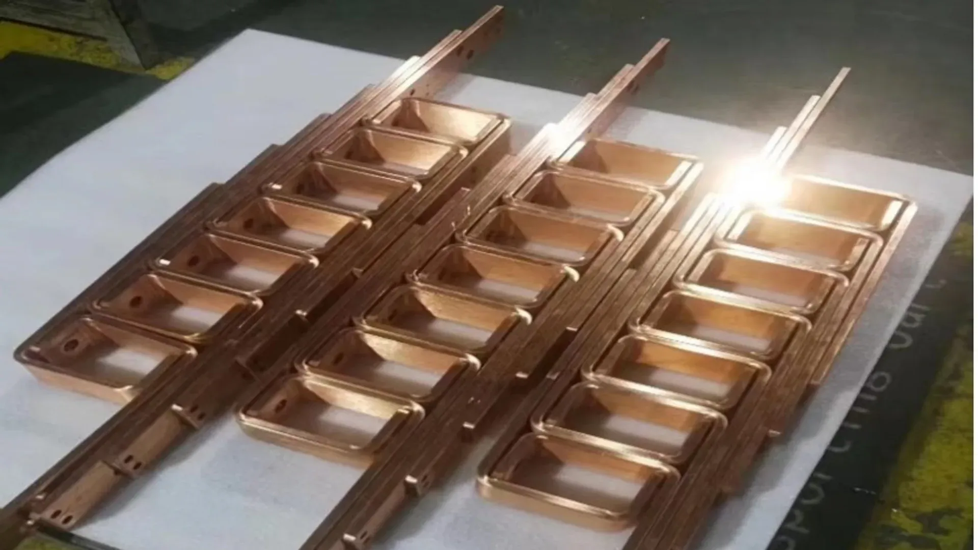
A transformer busbar processing machine should be specified as part of a heavy-copper workflow. Nominal force matters, but long-part support, terminal-hole accuracy, bend access, springback control and safe handling often determine whether the proposed cell can make the real component.
This is a production issue rather than a claim that one machine can resolve transformer supply constraints. In a January 2026 presentation, the U.S. Department of Energy identified transformers and breakers among the critical grid components needed for buildout, replacement and resilience in its transformer supply-chain work. A manufacturer adding capacity should still size equipment from its released conductor families and quality plan.
Translate finished terminals into process requirements
Start at the assembly interface. Transformer and busduct conductors may share copper stock, yet their finished geometry and production rhythm can be different.
Transformer terminal links often combine a connection pad, one or more bends and a long leg that must meet a bushing or winding lead. Busduct conductors tend to repeat along a product platform but may require controlled end preparation, splice-hole patterns and offsets between enclosure sections.
Create a part matrix with these fields:
| Finished-part requirement | Machine or cell implication |
|---|---|
| Long straight leg | Infeed, intermediate and outfeed support without scratching or permanent sag |
| Dense terminal holes or slots | Tool availability, positioning method and inspection access |
| Flat, vertical, Z or U bend | Tool geometry, opening, stroke and collision clearance |
| Twist or compound bend | Dedicated tool, controlled sequence and part support through rotation |
| Plated or insulated surface | Protected contact, operation sequence and handling controls |
| Large variation in part families | Program control, changeover method and flexible tooling storage |
The earlier guide to thick-copper transformer busbar fabrication addresses bend and terminal-quality mechanics. Use it after the route matrix identifies which features the proposed equipment must demonstrate.
Separate the machine envelope from the process envelope
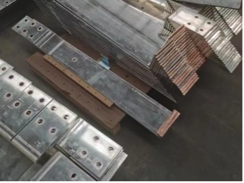
A specification such as “15 mm copper capacity” is incomplete. Ask whether that limit applies to punching, shearing, flat bending, vertical bending or only a particular material width and tool. The usable process envelope is the intersection of material size, tool geometry, access and finished-part clearance.
For repeated terminal-hole patterns, a dedicated CNC punching and shearing machine may provide a controlled route. The DHCNC-BP-60 publishes a maximum workpiece envelope of 6,000 × 200 × 15 mm, 600 kN nominal force and ±0.20 mm/m hole-pitch accuracy. These are machine specifications, not an acceptance result for a customer’s bar. The longest and thickest drawing still needs to be run with the ordered tools.
For formed terminals, the DHAC-BB-H servo-hydraulic bender publishes 400 kN nominal force, ±0.2° bending accuracy and ±0.02 mm Y-axis repeatability. A bend may remain outside scope if the tool cannot enter or withdraw from a closed shape, the finished leg collides with the frame, or the required inside radius is unavailable.
Write those geometric limits into the quotation. Do not reduce the decision to tonnage.
Design support and handling before cycle time
A long copper bar can meet every machine capacity number and still produce inconsistent parts if its free length pulls against the positioning or bending point. Support is therefore part of the process, not a logistics accessory.
Map the material path from stock rack to inspected part. Check:
- whether rollers or low-friction supports remain level with the machine datum;
- how the operator controls a long tail during punching and shearing;
- where a partly formed part rests between operations;
- whether two people or a lifting aid are needed after a bend shifts the center of gravity;
- how finished contact areas are kept away from steel chips, burrs and dirty surfaces.
The support layout must also allow measurement. If a long bar is forced flat on an unsuitable table for inspection, the result may hide distortion that returns after release.
Choose one combined workstation or a split cell
A combined punching, shearing and bending workstation can be effective for repair parts, prototypes and changing transformer designs. It reduces travel and keeps all basic processes available. Its production rate, however, depends on operator coordination and on whether different operations can proceed without waiting for the same fixture, program or inspection resource.
A split cell is appropriate when the hole-making workload is stable enough to occupy a dedicated CNC unit and formed parts need separate bend capacity. It also lets each machine carry more specialized tooling. The tradeoff is additional floor space, work-in-process, transfer handling and production control.
Compare both arrangements with a routed sample week. Include repeated busduct parts, a difficult transformer terminal and engineering-change work. Count transfers and first-piece approvals as well as machine motion.
Keep non-machine processes visible
Rigid busbar punching, shearing and bending do not complete every transformer or busduct conductor. Depending on the drawing, the route may also require milling, drilling, edge finishing, cleaning, plating, insulation, joining and electrical or dimensional testing.
Mark each process as one of four categories in the RFQ:
- performed by the proposed machine;
- performed by another machine supplied in the same project;
- performed by the buyer or a subcontractor;
- not required for the representative product family.
This prevents a complete “busbar line” proposal from being interpreted as including work that was never demonstrated or priced.
Run an acceptance trial that stresses geometry
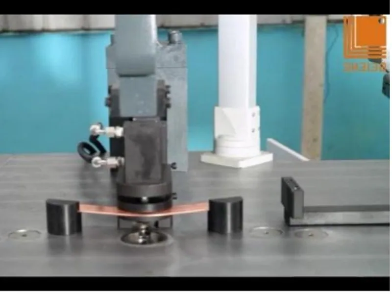
The trial set should include more than a short, flat sample. Choose at least one long conductor, one dense terminal-hole pattern and one bend with restricted access. If twist bending is required, include the actual material, length and orientation.
Use the buyer’s drawing revision and inspection method. Measure hole position from the specified datums, cut-end condition, bend angle and final assembly dimensions. Inspect contact faces and edges for damage caused by supports, clamps or transfer.
The FAT and SAT protocol explains how to preserve conditions and results across factory and site tests. For this application, the acceptance record should also identify the tool code, material lot, support arrangement and any manual correction used to pass the part.
Write the quotation around the full workflow
A comparable transformer busbar machine quotation should include the machine, defined tool set, stock support, finished-part handling, software files, electrical configuration, training and inspection responsibility. It should list unsupported features just as clearly as supported ones.
Use the transformer and busduct solution page to review the application context, then submit the part matrix and representative drawings. The useful supplier response is not “suitable for transformers.” It is a process route tied to named equipment, tools, limits and acceptance evidence.
Frequently Asked Questions (FAQs)
What machine functions are needed for transformer busbars?
Most rigid transformer busbars need controlled cutting, terminal holes and one or more flat, vertical, offset or twist bends. The exact machine combination depends on bar dimensions, terminal geometry, batch mix and whether drilling, milling, plating or assembly remain separate processes.
Is bending force the only specification that matters for thick copper?
No. Usable tooling space, bend radius, stroke, springback control, workpiece support and access around the finished geometry can be more restrictive than nominal force. Test the widest and most constrained buyer part.
Should transformer busbar punching and bending be performed on one machine?
One multi-function workstation can suit mixed, lower-volume work, while separate punching and bending machines can support parallel production and specialized tooling. Compare the complete routed part mix rather than assuming one arrangement is universally better.
What should a transformer busbar machine FAT include?
The FAT should use buyer-selected copper, drawings and tools, including a long part, a demanding terminal-hole pattern and a constrained bend. Inspect hole position, cut end, bend angle, final geometry and visible handling damage.
DHAC-BB-H Servo-Hydraulic Busbar Bender
Discover details, parameters, standard dies packages, and factory quotes.