
Flexible Busbar Selection Guide: Foil, Braided, and Laminated Connections
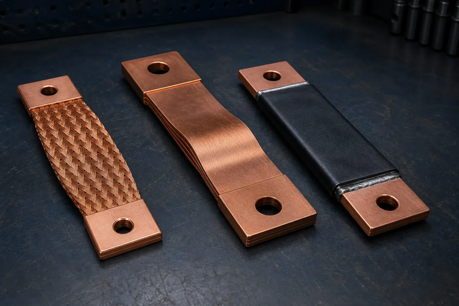
“Flexible busbar” describes a job, not a single construction. A braided copper strap, a stack of thin foils, and an insulated flexible laminate can all carry current while accommodating movement, yet they behave differently under vibration, thermal expansion, assembly error, and fault forces.
Good selection starts with the movement and interface. If the RFQ only states amperes, length, and hole size, the supplier is forced to guess how the connector will bend, how often it will move, and which terminal surface must stay rigid. Those guesses show up later as hot joints, work-hardened foil, overstressed braid, or an assembly that fits only when forced.
Start With the Movement the Connection Must Absorb
Separate the mechanical inputs before comparing products:
- Thermal expansion is usually slow and directional. Estimate relative movement between the connected components over the operating temperature range. The busbar expansion-joint and support guide shows how to calculate growth and define the fixed points before selecting a connector.
- Vibration adds frequency, acceleration, and cycle count. Transformer, vehicle, inverter, and switchgear environments are not equivalent.
- Assembly tolerance may be a one-time offset. The connector must fit without permanently preloading the terminals.
- Service motion applies when a door, removable module, or sliding assembly is operated repeatedly.
- Electromagnetic fault force can be brief but severe. Flexibility during normal operation does not mean the connector can be left unsupported during a fault.
Define displacement in axes and rotations, not only as “flexible.” Include the neutral installed position and any prohibited bend direction.
Flexible Constructions Are Not Interchangeable
Braided copper straps
Braids are made from many fine copper wires woven into a compliant strap. They can tolerate movement in multiple directions and are common for bonding, vibration isolation, and connections where geometric freedom matters. Their open construction, strand condition, end termination, and environmental exposure need careful review.
Stacked copper foil connectors
Foil connectors use multiple thin copper leaves joined into rigid terminal blocks. The free foil length can flex between the terminals while preserving a compact, low-profile current path. Leaf thickness, stack width, free length, terminal process, and bend direction all influence stiffness and fatigue.
Insulated flexible or laminated connectors
Some products combine thin conductors with an insulating envelope to provide controlled routing and touch protection. The design may resemble a flexible laminate, but it should not be confused with every low-inductance laminated busbar. The laminated busbar design guide focuses on conductor overlap, dielectric stack-up, and switching-loop performance rather than mechanical compliance alone.
| Construction | Mechanical behavior | Terminal challenge | Inspection emphasis |
|---|---|---|---|
| Braid | Multi-directional compliance | Strand-to-terminal connection | broken strands, termination integrity, finish |
| Stacked foil | Directional, tunable flexibility | joining a leaf stack to a rigid palm | layer alignment, joined zone, free length |
| Insulated flexible laminate | Controlled path with covering | seal and cutback at terminals | insulation, edge seal, terminal geometry |
Size the Electrical Path Without Ignoring Temperature
Conductor cross-section is only the first input. Heat is created in the flexible section and at the terminals, then removed through air, connected equipment, and any enclosure cooling. A short wide connector can behave differently from a long narrow connector with the same copper area.
The rating review should include:
- copper grade and effective conducting area;
- total path length and construction density;
- terminal overlap, finish, hardware, and contact pressure;
- ambient temperature and nearby heat sources;
- orientation, airflow, enclosure, and grouping;
- continuous, intermittent, and overload duty;
- allowed temperature rise at the flexible body and the joint;
- ageing or fatigue effects over the required service cycles.
Do not transplant an ampacity from a different supplier or installation. Use a product datasheet that states conditions, or validate a representative assembly. The nVent ERIFLEX flexible-busbar overview illustrates how construction-specific data belongs to a defined product family rather than the generic keyword.
Design the Terminal Before the Flexible Section
The terminal palm is where electrical, mechanical, and manufacturing requirements meet. Define its thickness, width, hole or slot pattern, edge distance, contact area, flatness, finish, and orientation. Also identify which component establishes the assembly datum.
A flexible section should transition into the rigid terminal without an abrupt strain concentration. The free length must not be consumed by a clamp, insulation boot, sharp edge, or installation bend. If the connector arrives twisted away from its intended neutral position, it will carry continuous preload before current is applied.
Terminal holes and profiles may be produced on a controlled punching and shearing workstation, but the joining of foil or braid to the terminal requires its own qualified process. One machine capability should not be represented as the complete flexible-busbar manufacturing route.
Match the Manufacturing Process to the Construction
Braided straps may use pressed, welded, or otherwise qualified end terminations depending on the supplier’s design. Foil stacks may use a joining process that consolidates the leaves at each terminal. Insulated constructions add sealing, cutback, and dielectric controls.
The drawing and process specification should control:
- conductor and terminal material;
- number and thickness of foils or braid construction;
- joined-zone length and allowable visual condition;
- free flexible length and neutral shape;
- terminal machining, deburring, and flatness;
- plating or other surface treatment;
- insulation material, edge seal, and terminal cutback;
- handling so the free section is not creased before assembly.
Claims about a particular diffusion-welding temperature, pressure, or strength should come from the qualified supplier procedure or validated research, not a generic equipment blog.
Inspect Flexibility, Terminations, and Electrical Consistency
Dimensional inspection confirms the connector can be assembled without preload. Visual inspection finds layer offset, damaged braid, sharp edges, cracks, contamination, coating damage, or an irregular joined zone. Electrical checks can include resistance or temperature-rise verification when required by the project.
For repeated motion, static pull or bend demonstrations are not enough. The qualification needs the specified displacement direction, frequency, temperature, and number of cycles, followed by inspection and electrical reassessment. Fault-force restraint also belongs to the assembly test plan.
Put the Right Fields in the RFQ
| RFQ field | What to provide |
|---|---|
| Geometry | terminal datums, installed length, orientation, keep-out zones, 2D/3D files |
| Electrical duty | current profile, voltage context, allowable temperature rise, fault inputs |
| Movement | axis, amplitude, rotation, frequency, cycles, neutral position |
| Environment | ambient range, enclosure, airflow, vibration, contamination, corrosion |
| Terminals | material, thickness, holes, flatness, finish, hardware interface |
| Insulation | touch-protection goal, dielectric specification, cutbacks, flame/environment needs |
| Validation | dimensions, resistance, temperature, mechanical cycling, documents |
| Supply | sample quantity, annual volume, packaging, change-control requirements |
Applications such as EV and new-energy busbar systems and utility-scale BESS may need different motion and thermal profiles even when the connector looks similar.
Know When a Rigid Busbar Is Better
Select a rigid busbar when the connection does not need movement compensation and precise geometry, structural support, short path length, or predictable assembly is more important. Select a low-inductance laminated busbar when current-loop geometry and electromagnetic performance dominate. Choose flexible construction when movement is real, quantified, and designed into the connector.
That decision should be made at system level. Replacing a cable or rigid bar with a flexible busbar without recalculating terminal forces, protection, thermal behavior, and support merely moves the uncertainty into a more expensive component.
Frequently Asked Questions (FAQs)
What is the difference between braided and foil flexible busbars?
A braided busbar uses woven copper strands and is highly compliant in several directions. A foil connector uses stacked thin copper leaves joined at rigid terminals and can be tuned for a defined movement direction, current path, and package. Their terminal processes and inspection methods differ.
When should a flexible copper busbar replace a cable?
Consider it when a low-profile high-current path needs controlled geometry, repeatable terminals, reduced assembly variation, or compensation for vibration and thermal movement. A cable can remain preferable when routing flexibility, standard connectors, or field replacement dominate.
How is a flexible busbar current rating determined?
Start with conductor area and material, then assess length, construction, terminal resistance, enclosure cooling, ambient temperature, orientation, duty cycle, and permissible temperature rise. The rating should come from supplier data or representative system testing under defined conditions.
Can one flexible busbar absorb vibration and thermal expansion?
It can be designed for both, but the displacement magnitude, direction, frequency, cycle count, and short-circuit loading must be specified. A connector that is soft in one axis may be stiff or vulnerable in another.
What information belongs in a flexible busbar RFQ?
Provide terminal-to-terminal geometry, material, current and duty, temperature limits, movement direction and amplitude, vibration, fault forces, insulation and finish, hole pattern, installation constraints, test requirements, documentation, and annual quantity.
DHCNC-BP-60 CNC Punching & Shearing Workstation
Discover details, parameters, standard dies packages, and factory quotes.