
What Busbar Design and Processing Requirements Do Utility-Scale BESS Projects Demand in 2026?
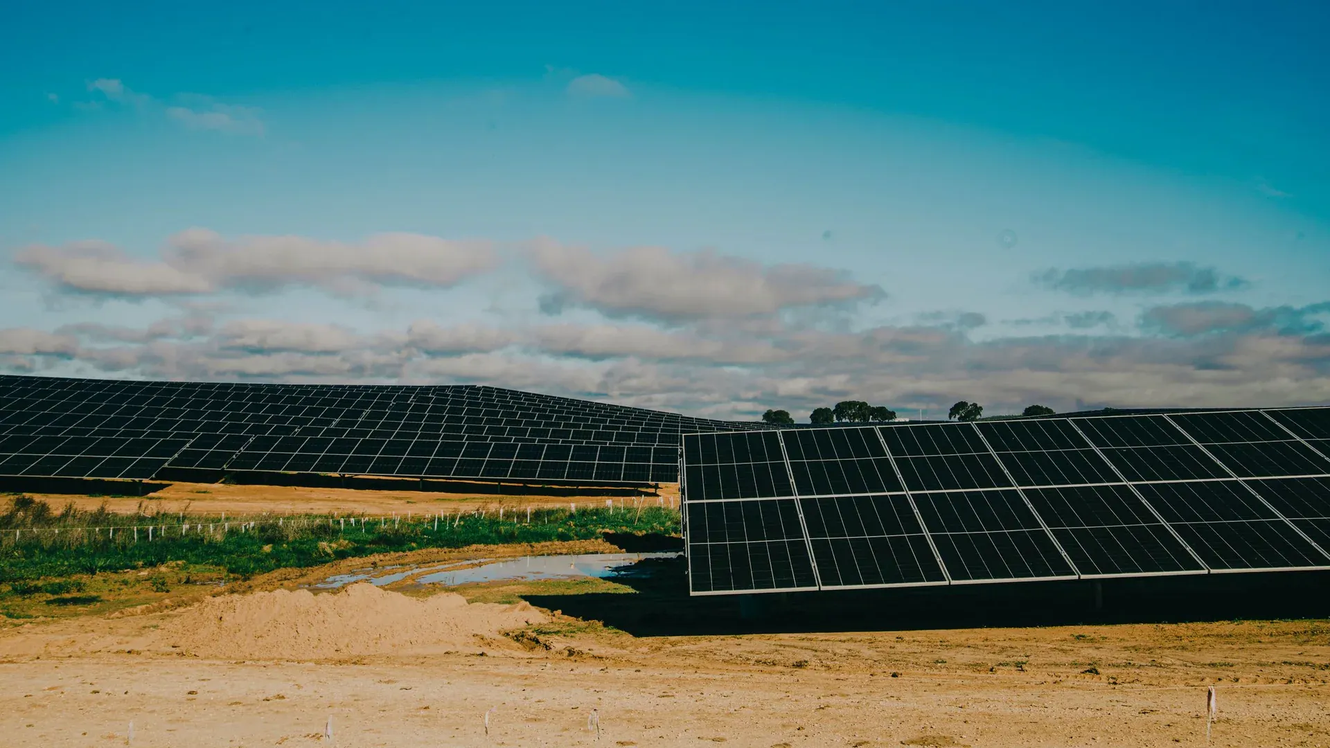
The global battery energy storage market added capacity at a rate in early 2026 that surprised even bullish forecasters. India’s BESS additions surged 941% quarter-over-quarter in Q1 2026, per IBEF, as grid-scale storage transitioned from pilot projects to commercial deployment. In the United States, Illinois’ Clean & Reliable Grid Affordability Act (CRGA) took effect on June 1, 2026, creating state incentives for new utility-scale storage projects that are already drawing developer interest. The European Commission is targeting 200 GW of installed battery storage capacity by 2030, up from approximately 55 GW in 2025. These numbers converge on a single fabrication challenge: every megawatt-hour of BESS capacity requires busbars—DC-link interconnects between battery racks, combiner boxes, and power conversion systems—that must handle 1,000-1,500V DC at continuous currents from 800A to 4,000A while meeting fire safety standards written for the unique hazards of lithium-ion battery installations. At DH CNC, BESS-related busbar tooling inquiries have tripled since Q4 2025, and the technical requirements our engineering team is fielding are materially different from standard switchgear busbar specifications.
Why Is 1,500V DC the Defining Voltage Standard for BESS Busbar Design?
The BESS industry has largely converged on 1,500V DC as the standard DC-link voltage for utility-scale systems above 50 MW. The rationale is straightforward economics: doubling the DC bus voltage from 750V to 1,500V halves the current for equivalent power throughput, which reduces I²R losses by 75% and allows smaller conductor cross-sections for the same thermal performance. But the insulation coordination requirements that this voltage imposes on busbar design are substantial—and many fabricators entering the BESS market from traditional AC switchgear backgrounds underestimate them.
Under IEC 60664-1:2020, a 1,500V DC busbar at Pollution Degree 2 (the minimum classification for a BESS container environment, which may experience condensation, dust ingress, and salt spray in coastal installations) requires:
| Design Parameter | 800V DC (EV Reference) | 1,500V DC (BESS) | Standard |
|---|---|---|---|
| Minimum creepage (bare copper, PD2) | 4.0 mm | 8.0 mm | IEC 60664-1 Table F.2 |
| Minimum clearance (reinforced, sea level) | 4.2 mm | 8.4 mm | IEC 60664-1 Table F.1 |
| Clearance at 3,000m altitude | 6.1 mm | 12.2 mm | IEC 60664-1 Table A.2 |
| Comparative Tracking Index (CTI) | ≥600 (Group I) | ≥600 (Group I) | IEC 60112 |
| Inter-conductor air gap (DH CNC guideline) | 6-8 mm | 12-16 mm | Based on field concentration modeling |
| Typical busbar width for 800A continuous | 60-80 mm | 100-160 mm | Wider for creepage extension |
The creepage requirement in particular drives busbar geometry in ways that impact material cost. An 8.0mm creepage path on the surface of a flat busbar means that any bolt hole, slot, or edge within 8.0mm of an adjacent conductor of different polarity must be accounted for in the insulation design. In practice, this forces wider busbar cross-sections, longer creepage slots, and in many 1,500V designs, the addition of insulating barriers (typically glass-reinforced polyester or Nomex sheet) between phases—all of which increase fabrication complexity.
Our engineering team’s practical recommendation: for BESS DC-link busbars above 1,000V, design for a minimum 12mm inter-conductor gap with conformal coating on all bare copper surfaces (which reduces the effective Pollution Degree from 2 to 1 under IEC 60664-1 and cuts creepage requirements by roughly 60%). This is not the cheapest approach to material cost, but it is the most reliable approach to field performance—and in a BESS installation where a busbar insulation failure can trigger a cascade that propagates through adjacent battery racks, reliability is the dominant design constraint.
What Current Ratings Do BESS Busbars Need—and How Does That Drive Conductor Sizing?
The current ratings in utility-scale BESS busbar systems span a wider range than most switchgear applications, and the sizing methodology must account for the specific thermal environment of a sealed, outdoor BESS container.
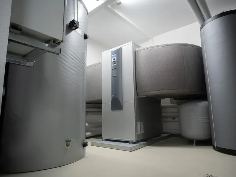
A typical 4.0 MWh BESS container (using the ABB reference architecture) contains eight battery racks, each delivering approximately 500 kW at nominal voltage. The DC combiner busbar that aggregates current from four racks before the DC-DC converter stage carries roughly 800-1,200A continuous, while the main DC-link busbar between the DC combiner and the PCS (Power Conversion System) can carry 2,000-4,000A depending on system configuration. These current levels, combined with the 1,500V voltage rating, produce busbar cross-sections that are physically large—and therefore expensive in copper.
| BESS Busbar Position | Typical Continuous Current | Recommended Copper Cross-Section | Typical Dimensions (W x T) | Weight per Meter |
|---|---|---|---|---|
| Battery rack output (per rack) | 200-400A | 50-100 mm² | 40mm x 3mm to 60mm x 5mm | 1.1-2.7 kg/m |
| DC combiner (4 racks aggregated) | 800-1,200A | 200-300 mm² | 80mm x 5mm to 120mm x 6mm | 3.6-6.4 kg/m |
| Main DC link (combiner to PCS) | 2,000-4,000A | 500-1,000 mm² | 120mm x 10mm to 200mm x 10mm | 10.7-17.8 kg/m |
| PCS AC output (480V/690V) | 1,500-3,000A | 375-750 mm² | 100mm x 8mm to 160mm x 10mm | 7.1-14.2 kg/m |
At a July 2026 copper price of approximately $11,000-12,000 per ton (LME cash plus fabrication premium), a single 4.0 MWh BESS container contains roughly 150-250 kg of fabricated copper busbar—representing $1,650-3,000 in raw copper material cost before fabrication. A 100 MW / 400 MWh BESS installation requires roughly 25 such containers, for a total copper busbar requirement of 3.75-6.25 metric tons and a material cost of $41,000-75,000—before accounting for the CNC processing, plating, insulation, and quality assurance that transforms raw copper bar into a UL 9540-compliant busbar assembly.
This is where nesting optimization and waste reduction—topics we cover in depth in our 3D nesting and copper waste reduction analysis—directly impact BESS project economics. At a 12% scrap rate (typical for manual busbar processing), a 100 MW BESS project wastes approximately $5,000-9,000 in copper. At a 2.5% scrap rate with CNC nesting optimization, that waste drops to roughly $1,000-1,900—a savings of $4,000-7,000 per project in material alone.
How Do NFPA 855 and UL 9540A Reshape Busbar Safety Requirements Inside BESS Containers?
Fire safety is the defining regulatory concern for BESS installations in 2026, and it has direct implications for busbar design and material selection that go beyond standard electrical codes.
NFPA 855 (2026 Edition) establishes safety distances between ESS units and adjacent equipment, requires explosion prevention analysis for enclosed BESS containers, and in its 2026 update, introduces stricter requirements for gas management and thermal runaway propagation prevention. For busbars inside a BESS container, the practical implications include:
Flame-Retardant Insulation Materials. Busbar insulation inside a BESS enclosure must meet a minimum of UL 94 V-0 flammability rating and be rated for continuous operating temperature at the maximum ambient the container can experience—typically +50°C with solar loading on the container exterior. This rules out standard PVC insulation (typically rated to +70°C but with poor flame performance) and pushes designs toward Nomex 410 (220°C thermal class) or polyimide film (180°C+ continuous) for laminated busbar constructions.
Clearance to Container Walls. NFPA 855 specifies minimum 3-foot (0.91m) clearance between BESS units and adjacent structures unless a 1-hour fire-rated barrier is installed. Inside the container, this translates to a requirement that busbar runs maintain adequate separation from container walls and that busbar support insulators be made of non-combustible materials (typically ceramic or glass-reinforced epoxy rather than thermoplastic).
Arc Flash Containment. In the confined space of a BESS container, an arc flash event on a 1,500V DC busbar can ionize the air and create a conductive plasma path that sustains the arc at currents exceeding 100 kA. The busbar design must incorporate arc-resistant barriers between phases and between the busbar assembly and the container enclosure. At DH CNC, we recommend glass-reinforced polyester (GRP) barriers with a minimum 3.2mm thickness for phase-to-phase separation in BESS busbar assemblies above 1,000V DC.
UL 9540A—the test standard for evaluating thermal runaway fire propagation in BESS installations—is now required by most Authorities Having Jurisdiction (AHJs) for utility-scale projects. While UL 9540A primarily tests the battery cells and modules, the standard’s scope extends to “all electrical components within the ESS enclosure,” including busbars. Our recommendation for BESS busbar fabricators: select materials and designs that have been evaluated as part of a UL 9540-certified ESS system, and document that evaluation in the project’s Hazard Mitigation Analysis (HMA) as required by NFPA 855.
What Fabrication Precision Does 1,500V DC Busbar Assembly Demand?
The jump from 800V to 1,500V DC more than doubles the voltage stress on busbar insulation, but the precision requirements scale non-linearly. At 1,500V, a localized geometric defect that would be a cosmetic issue at 480V becomes a partial discharge initiation site.
Our factory’s internal specification for BESS busbar fabrication builds on the same precision framework we apply to 800V EV busbars—with additional margin for the higher voltage:
| Fabrication Parameter | Standard Switchgear (480V AC) | 800V EV Busbar | 1,500V DC BESS Busbar |
|---|---|---|---|
| Bend angle tolerance | ±0.5° | ±0.2° | ±0.2° |
| Edge radius (minimum) | 0.3 mm | 1.0 mm | 1.5 mm |
| Maximum burr height | 0.1 mm | 0.05 mm | 0.05 mm |
| Flatness across 300mm | 0.5 mm | 0.15 mm | 0.15 mm |
| Hole position accuracy | ±0.2 mm | ±0.1 mm | ±0.1 mm |
| Surface roughness (Ra) on contact surfaces | 6.3 μm | 3.2 μm | 1.6 μm |
| Contact resistance (bolted joint) | <50 μΩ | <25 μΩ | <15 μΩ |
The lower contact resistance requirement for BESS busbar joints deserves explanation. In a 4,000A DC-link busbar, a bolted joint with 50 μΩ resistance dissipates I²R = 4,000² × 50×10⁻⁶ = 800 watts—roughly the output of a small space heater, concentrated at a single joint. Reduce that to 15 μΩ, and the dissipation drops to 240 watts. Over the 20-year design life of a utility-scale BESS installation, the cumulative energy loss difference at a single joint can exceed $10,000 in electricity costs at typical industrial tariffs—and a BESS container has dozens of such joints.
Our CNC busbar bending center (DHAC-BB-H) is calibrated to hold the ±0.2° bend angle tolerance and positional accuracy required for BESS busbar fabrication. For the surface finish requirements—particularly the 1.6μm Ra on contact surfaces—we recommend post-machining electropolishing or precision vibratory finishing, which our DHCNC-BP-60 integrated workstation supports as part of a complete fabrication cell when paired with the appropriate finishing equipment.
What Is the Procurement Playbook for BESS Busbar Fabrication Capacity?
For manufacturers and project developers evaluating BESS busbar supply strategies, the decision framework in 2026 is shaped by three intersecting constraints: rising copper costs, tightening fire safety regulations, and scaling production volumes that are beginning to justify dedicated fabrication capacity.
Build vs. Buy Decision. For a BESS integrator producing fewer than 500 containers per year, outsourcing busbar fabrication to a qualified supplier is typically the right economic choice. The equipment investment ($60,000-$180,000 for a CNC busbar processing system) does not amortize favorably at low volumes. For integrators above 1,000 containers annually, the math flips: in-house fabrication recovers equipment cost within 18-24 months through material utilization savings and elimination of supplier margin, as we analyzed in our CNC busbar machine ROI model.
Supplier Qualification. When qualifying an external busbar supplier for BESS applications, verify that they have in-house UL 9540A awareness, documented partial discharge testing capability per IEC 60270, and experience fabricating busbars with the specific insulation materials (Nomex, polyimide, GRP barriers) required for BESS fire safety compliance. A supplier whose primary experience is commercial switchgear busbars at 480V AC will have a learning curve on 1,500V DC BESS requirements—and that learning curve produces quality escapes.
Material Strategy. The copper content per MW of BESS capacity is high enough that material procurement strategy directly impacts project economics. Our recommendation: negotiate copper supply agreements indexed to LME with a fixed fabrication premium, rather than purchasing at spot prices. The fixed premium provides budget certainty; the LME index ensures you are not locked into a price that diverges from market reality. For our customers in the renewable energy and BESS sector, we provide material yield analyses that quantify the copper savings achievable with CNC nesting optimization on their specific busbar designs.
BESS teams comparing compliant interconnect options can use the flexible busbar selection guide to separate movement accommodation from low-inductance requirements. Where commutation-loop behavior drives the design, the laminated busbar manufacturing guide explains the geometry and process controls to specify.
Frequently Asked Questions (FAQs)
What voltage rating do utility-scale BESS busbars require in 2026?
Utility-scale BESS installations in 2026 operate at DC link voltages of 1,000V to 1,500V DC, with the industry trending toward 1,500V as the dominant standard for systems above 50 MW. Per IEC 60664-1, a 1,500V DC busbar in Pollution Degree 2 requires minimum 8.0mm creepage for uncoated copper conductors. With conformal coating, this can be reduced to approximately 3.5mm using the Pollution Degree 1 equivalent protection factor. Clearance through air for reinforced insulation at 1,500V DC is 8.4mm at sea level, derating to 12.2mm at 3,000m elevation. These dimensions are substantially larger than the 4.0mm/6.1mm requirements for 800V EV busbars and demand dedicated tooling setups on CNC fabrication equipment.
What fire safety standards apply to busbars inside BESS containers?
NFPA 855 (2026 edition) governs the installation of stationary energy storage systems and imposes specific requirements for electrical equipment inside BESS enclosures. UL 9540A provides the test methodology for evaluating thermal runaway fire propagation in BESS installations. For busbars specifically, UL 9540 certification for the complete integrated ESS system requires that internal power distribution conductors—including busbars—withstand the thermal and mechanical stresses of a worst-case thermal runaway event without contributing to fire propagation. At DH CNC, we recommend busbars for BESS applications use Class H (180°C) or Class N (200°C) insulation materials and be fabricated from ETP copper (C11000) with electroless nickel plating for corrosion resistance in the humid, salt-spray environments where many BESS containers operate.
How does BESS busbar fabrication differ from standard switchgear busbar production?
BESS busbar fabrication differs in four critical dimensions: (1) DC voltage ratings of 1,000-1,500V require larger creepage and clearance distances than AC switchgear at equivalent RMS voltages, demanding wider busbar geometries and larger bend radii; (2) continuous current ratings of 800-4,000A in BESS DC links often require laminated busbar designs with interleaved positive and negative conductors to minimize stray inductance, whereas switchgear busbars are typically single-layer; (3) thermal cycling in BESS applications—from -20°C cold start to +50°C continuous operation inside a sealed container—imposes mechanical stress on bolted busbar joints that switchgear in climate-controlled enclosures does not experience; (4) copper content per MW in BESS is roughly 1.5-2x that of equivalent AC switchgear, making material utilization efficiency even more critical.
DHAC-BB-H Servo-Hydraulic Busbar Bender
Discover details, parameters, standard dies packages, and factory quotes.