
Busbar Thermal Expansion: Sizing Movement and Expansion Joints
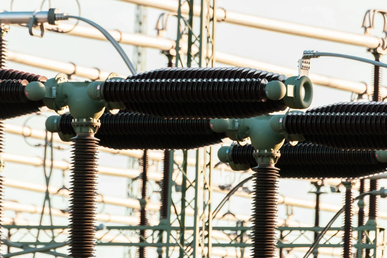
A bar that fits comfortably between two terminals when cold may try to become several millimeters longer under load. If both ends are restrained, that movement does not disappear. It becomes load on the conductor, joints, supports, and connected equipment.
The right starting point for a busbar expansion joint is therefore a movement calculation and a sketch of the restraints. Selecting a flexible connector first can leave the most important questions unanswered: which direction must it move, how far, how often, and against what reaction force?
The substation photograph illustrates conductors and supports, not a prescribed expansion-joint design. Low-voltage bars, busduct connections, and outdoor conductors require their own verified arrangements.
Calculate Movement Before Selecting a Connector
For a uniformly heated, freely expanding bar, the first estimate is:
ΔL = α × L × ΔT
Here, ΔL is the change in length, α is the linear expansion coefficient, L is the reference length, and ΔT is the change in conductor temperature. Use consistent units. A temperature difference of 60°C is a difference of 60 K; it is not an absolute temperature of 60 K.
The CDA C11000 material entry gives thermal expansion over specified temperature intervals. Its 68–212°F coefficient of 9.4 × 10⁻⁶ per °F corresponds to approximately 16.92 × 10⁻⁶ per K. A rounded value of 17 × 10⁻⁶/K is used in the following illustrative calculation, not as a specification for every copper alloy and temperature range.
For a 3,000 mm bar with an assumed 60 K rise:
ΔL = 17 × 10⁻⁶ × 3,000 × 60 = 3.06 mm
That is the free growth of the bar under the assumptions. It is not automatically the required travel rating of a connector. Assembly tolerance, the movement of the supporting structure, terminal motion, and the chosen fixed points still have to be included.
If temperature varies strongly along the run, divide it into appropriate sections or use a model that captures the distribution. Applying the hottest local temperature to the entire run may be conservative for growth but can misrepresent where movement and stress occur.
Draw the Fixed Points and the Permitted Directions
Mark each support as fixed, sliding, or otherwise movement-permitting according to its verified design. Then mark the terminals and any building or equipment interfaces. A symbol on a drawing is only useful if the physical support actually permits the stated movement after installation.
With one end fixed and the other free, the idealized growth appears at the free end. With a central fixed point and symmetrical, freely sliding halves, each end moves away from the center. With both ends fixed, the simple free-expansion result describes the displacement being restrained; it does not directly calculate the resulting stress.
The supporting structure also moves. For a simplified comparison along the same axis, relative growth is the conductor’s expansion minus the relevant structural expansion. The two components may have different lengths, coefficients, and temperatures. Do not simply subtract the copper and steel coefficients while assuming the frame reaches the conductor temperature.
Dedicated movement hardware exists for specific systems. For example, PLP’s expansion busbar support coupler is an application-specific substation component. Its existence illustrates why motion is a designed function; it does not make its dimensions or loading rules transferable to a switchboard.
An Expansion Joint Is Not a Loose Bolted Joint
An ordinary bolted electrical connection relies on its specified clamping condition. Allowing that interface to slip unpredictably can disturb contact pressure and surface condition. Loosening the bolts to accommodate thermal movement changes the electrical joint as well as its mechanical behavior.
The thermal-expansion discussion in Copper for Busbars warns that longitudinal movement can produce slip and loosening, and describes providing flexibility elsewhere in a long run. That distinction is central: retain the intended electrical contact while accommodating movement in a suitable element.
Possible arrangements include qualified flexible links, shaped conductor sections, or system-specific sliding/expansion assemblies. Their suitability depends on current, temperature, mechanical loading, and the permitted motion. The flexible busbar selection guide compares connector constructions; it should follow, not replace, the movement assessment.
Keep ordinary terminal preload and surface preparation under the joint contact-resistance controls. A movement solution should not silently undermine them.
Turn Displacement Into a Connector Specification
A request for “a flexible link for 3 mm expansion” is incomplete. Specify the operating envelope and identify the reference installation position.
| Required input | Why it changes the selection |
|---|---|
| Axial, lateral, and angular motion | A connector can be compliant in one direction and stiff in another |
| Cold installation and hot operating positions | Travel must remain available on the correct side of the neutral position |
| Expected thermal cycles and other movement | Slow expansion and continuous vibration impose different demands |
| Current and temperature limits | Flexible construction still needs a qualified thermal rating |
| Fault duty and restraints | Normal flexibility must coexist with short-circuit loading |
| Terminal geometry and reaction-load limits | The connected equipment must tolerate the transmitted force |
| Environment and insulation requirements | Corrosion, contamination, and barriers can affect the arrangement |
Ask the connector supplier to state which combinations are permitted. A maximum axial travel and a maximum lateral offset listed separately may not be allowed simultaneously. Likewise, a static installation offset is not necessarily an acceptable repeated operating stroke.
For a transformer or busduct interface, agree where the mechanical responsibility changes between suppliers. Neither party should assume the other has provided all necessary movement accommodation.
Check Movement Across Assembly, Service, and Faults
The installation check should confirm support orientation, available travel, terminal alignment, and clearance throughout the permitted motion. An installer should not need to force the bar into position and consume the intended expansion allowance before the equipment is energized.
During design validation, consider both the warm and cold extremes. Verify that conductors cannot contact neighboring phases, barriers, or grounded structures as they move. Include the effects of flexible-link geometry and any insulation that could rub or become trapped.
Normal thermal movement and fault loading are separate load cases. A support arrangement that slides correctly during slow expansion still needs evidence for its short-circuit duty. Testing and assessment belong to the responsible electrical and mechanical engineering team; live adjustment of supports is not a troubleshooting method.
Record the approved installation position and the dimensions that the workshop must preserve. The final drawing should show where movement is expected, where it is restrained, and which features must not be altered. That makes thermal expansion a controlled part of the assembly rather than a problem discovered at the terminals.
Frequently Asked Questions (FAQs)
Can loose bolts allow a busbar to expand safely?
Not in an ordinary bolted electrical joint. Its clamping condition is part of the joint design. Provide movement through a qualified expansion arrangement rather than reducing contact pressure to create uncontrolled slip.
Does every meter of busbar need an expansion joint?
No universal spacing applies. Required movement depends on the free length, temperature change, fixed points, support system, and connected equipment. Use those conditions to determine whether and where compensation is needed.
Should the calculation use ambient temperature or conductor temperature?
Use the relevant conductor temperature change for conductor expansion. Ambient conditions help establish that temperature, but current heating can make the bar substantially different from the surrounding air or support frame.
Can a flexible connector take movement in every direction?
Not necessarily. Specify axial, lateral, and angular movement separately and obtain the connector's permitted combinations, cycle capability, and terminal-load limits.