
CNC Busbar Machine Installation: A Site-Readiness Checklist
Installation delays usually begin before the truck arrives. A doorway is narrower than the packed machine, a disconnect is on the wrong side, the lifting contractor has no approved pick information, or test copper is still on order. None of these problems is solved by having a commissioning engineer wait on site.
A CNC busbar machine installation should pass a documented readiness gate before shipment and a final site check before arrival.
Freeze the Controlled Installation Inputs
Request the final, revision-controlled installation pack early enough for local review. It should include the machine and shipping dimensions, mass, lifting or handling instructions, general arrangement, service clearances, access panels, operator zone, material infeed and outfeed, anchoring or leveling requirements, and specified utilities.
Do not design the site from an early sales drawing. Record document number and revision on the installation checklist, and require the supplier to notify the buyer of changes that affect site work.
Create a responsibility matrix for:
- unloading and transport from receiving point;
- lifting equipment, spreader or specialist rigging;
- floor assessment, foundation, anchors and grout if specified;
- electrical supply and final connection;
- air, hydraulic medium, extraction or network services if specified;
- machine assembly, leveling and commissioning;
- local guarding, barriers and integration;
- test material, gauges, operators and waste handling;
- permits, inspections and destination compliance.
The import CNC busbar machine procurement guide should be used to align these site duties with the freight and commercial scope.
Survey the Entire Movement Route
Measure from the actual unloading point to the final machine position. Check yard access, dock capacity, door width and height, turns, ramps, columns, overhead obstructions, floor transitions, elevator capacity if relevant and the space needed to remove packing.
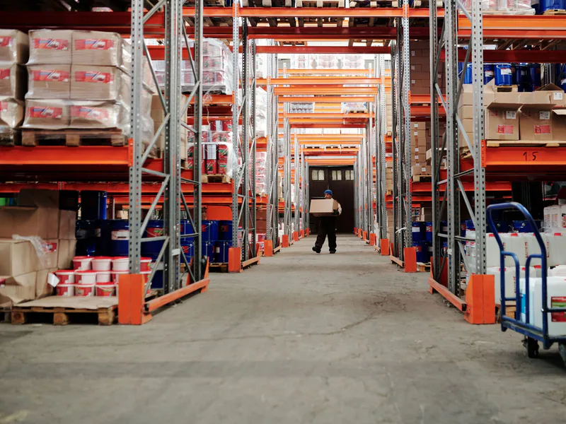
The route survey should consider the packed unit and handling equipment together. A machine may fit through a doorway while the forklift, skates or lifting frame cannot turn. Confirm surface load and condition with qualified site and rigging professionals.
Establish exclusion zones and traffic control for the move. Separate pedestrians, routine production and stored material from the rigging path. Plan where packing will be removed and how it will be disposed of without blocking the installation area.
Okuma’s CNC machine installation checklist provides a useful general reminder to plan utilities, foundation, delivery path and environmental conditions. The supplier’s final instructions and the site’s engineering review remain controlling.
Confirm the Footprint, Floor and Service Envelope
Mark the machine footprint, operator position, electrical cabinet access and maintenance clearances on the floor. Model the full movement of bars, doors, guards, removable tooling and maintenance components. Leave a safe route for incoming material and finished parts.
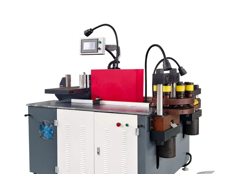
For planning reference, the DH303-8P multi-function busbar processing machine lists approximate machine dimensions of 1,750 × 1,350 × 1,500 mm and mass of 2,200 kg. These values do not include the transport package, handling equipment or a site-specific service envelope. The final supplied drawing governs.
Do not infer foundation or floor adequacy from machine mass alone. Dynamic loading, foot locations, slab condition, anchors and local construction rules need qualified evaluation. Record inspection and approval rather than using “floor looks strong” as a readiness item.
Match Electrical Service to the Delivered Configuration
Confirm voltage, frequency, phases, full electrical data, protective conductor and disconnecting requirements on the final electrical documents. The DH303-8P product specification lists 11.37 kW total motor power and a 380 V supply that can be customized; neither value is a cable or breaker selection.
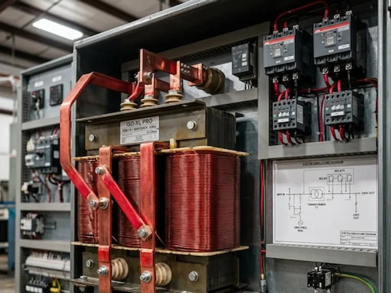
A qualified local electrical professional should determine supply conductors, overcurrent protection, disconnect placement, earthing or grounding, transformer needs and final connection under applicable code and site conditions. Confirm the actual ordered voltage before the machine leaves the factory.
If the facility supply differs from the standard configuration, use the voltage-modification planning guide to organize questions about transformer, control voltage, frequency and documentation. Do not energize until electrical inspection and supplier pre-start conditions are complete.
Prepare Only the Utilities the Machine Requires
Review specified hydraulic fluid, compressed air, cooling, ventilation, extraction and environmental limits. Avoid installing a generic service just because a similar machine uses it. Record connection type, pressure or quality range, consumption, isolation point and responsible party from the approved documents.
Control dust, moisture, temperature extremes, corrosive exposure and nearby processes that can affect electronics, hydraulics, measuring equipment or copper surface quality. Provide task lighting without creating glare at the HMI or inspection position.
Network and remote-support connections require buyer IT approval. Decide whether the machine will be isolated, locally networked or permitted controlled remote access, then prepare the approved ports, accounts and support method before commissioning.
Design Safe Copper Flow Around the Machine
Map raw stock from storage through processing to the next operation. Long, heavy or flexible bars need supported movement and clear space on both sides of a workstation. Define racks, rollers, carts, lifting aids and scrap containers without obstructing emergency access or electrical cabinets.
Check the largest and the most common bars, not only a nominal size. Observe how an operator will orient material, retrieve tools, unload parts and move remnants. If two people are expected to handle specific work, make that method explicit in the risk assessment and training plan.
Prepare traceable test material and representative drawings for commissioning. Arrange calibrated or controlled inspection equipment and a location where samples can be checked without interrupting the installation zone.
Coordinate Energy Control and Contractors
Installation and commissioning can expose workers to electrical, hydraulic, pneumatic, gravity and mechanical energy before normal production safeguards are fully established. The site must coordinate supplier personnel, electricians, riggers and its own authorized employees.
For US workplaces, OSHA’s control-of-hazardous-energy standard includes provisions relevant to servicing, new installations and outside personnel. Use the machine-specific energy sources, supplier documentation and site procedure to develop the actual control method. Never improvise isolation or ask a visiting technician to work under an undefined program.
Agree who controls keys, verifies isolation, releases the area for energization and authorizes transition from installation to testing. Keep this transition distinct from final production release.
Hold a Readiness Gate Before Arrival
About seven days before arrival—or earlier when open work needs more time—review every requirement with evidence.
| Gate item | Acceptable evidence |
|---|---|
| approved layout and revision | signed drawing reference |
| unloading and internal route | measured route survey and rigging plan |
| floor/foundation | qualified approval and completed work |
| electrical and other utilities | inspection or completion record |
| contractors and schedule | named people, scope and permits |
| energy-control coordination | approved procedure and briefing plan |
| material and inspection | identified copper, drawings and gauges |
| documents and backups | received-document register |
Classify open items as blocking arrival, blocking energization, blocking test operation or closable before production release. This prevents a missing training room from delaying unloading while ensuring an incomplete protective connection does block energization.
Site readiness ends when the machine can be received and installed under controlled conditions. Capability and final handover are then verified through the CNC busbar machine FAT/SAT protocol, not assumed from a successful lift.
Frequently Asked Questions (FAQs)
What must be ready before a CNC busbar machine arrives?
Approve the final installation drawing, survey the unloading and movement route, confirm floor and clearances, complete specified utilities, coordinate lifting and energy control, prepare safe material flow, and assign installation responsibilities.
Can machine nameplate power be used to size the facility breaker?
No. Nameplate and product data are inputs only. A qualified local electrical professional must use the final electrical documentation, installation method, applicable code, protective-device requirements and site conditions.
Who is responsible for rigging and foundation design?
The contract responsibility matrix should say. The machine supplier provides final dimensions, mass, center-of-gravity or lift information and foundation requirements; qualified local specialists design and execute the site work.
When should the installation-readiness review take place?
Conduct formal reviews before shipment release and again about seven days before planned arrival, leaving enough time to close blocked utilities, route, lifting, contractor, safety and material-preparation items.
DH303-8P 3-in-1 CNC Busbar Processing Machine
Discover details, parameters, standard dies packages, and factory quotes.