
UL 891 Switchboard Busbar Requirements: A Fabrication and Verification Guide
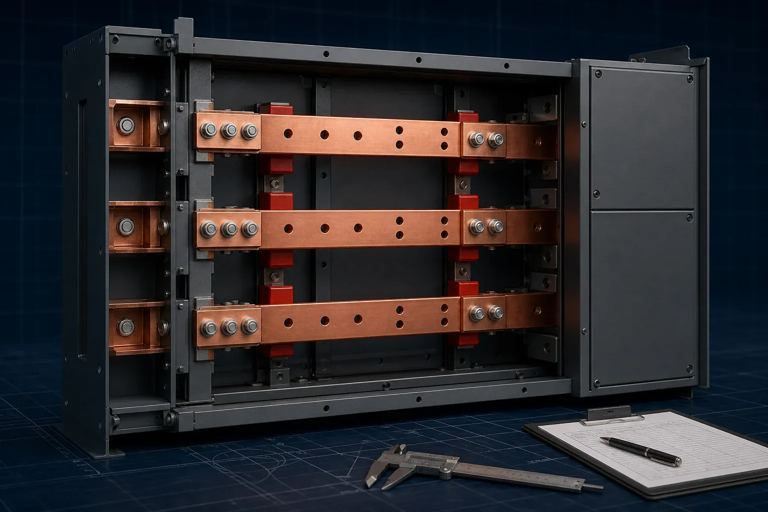
UL 891 compliance is not created at the punching machine, and it is not proven by measuring one finished copper bar. It begins with the correct equipment classification and an approved switchboard design. Fabrication then has to reproduce that design consistently, without changing the conductor geometry, joint interfaces, supports, or insulation system on which the evaluation depends.
That distinction matters to both switchboard manufacturers and busbar suppliers. A supplier can control material identity, hole location, cut edges, bend geometry, contact surfaces, and production records. It cannot independently declare that a completed switchboard complies with UL 891. The final evaluation belongs to the assembly program and the qualified certification body.
Start With the Equipment Classification, Not the Busbar Drawing
The first question is not “What copper size should we punch?” It is “What equipment are we building?” Switchboard, switchgear, panelboard, and busway are not interchangeable commercial labels. The classification affects the applicable standard, construction rules, test evidence, and marking route.
UL’s General Coverage Program for UL 891 provides a public entry point for switchboard manufacturers. Before releasing copper drawings, the project team should document at least:
- the equipment category and intended evaluation program;
- system voltage, frequency, phases, wires, and grounding arrangement;
- continuous-current and short-circuit ratings required by the assembly design;
- indoor or outdoor use and any environmental constraints;
- service-entrance or other project-specific functions;
- destination market, authority having jurisdiction, and certification-body contact;
- the controlled drawing set and the organization authorized to approve changes.
If the equipment classification is still being debated after fabrication starts, a correctly made busbar can still become the wrong part.
Turn the Approved Design Into a Fabrication Work Package
The fabrication work package should translate the released switchboard design into instructions that production and inspection can execute. It is more than a PDF outline of the copper bar.
Design information the assembly engineer must control
The assembly design determines the conductor arrangement, current path, spacing, support system, joint concept, protective-device interface, and verification basis. Fabricators should not infer these details from an earlier project or “improve” them on the shop floor.
The drawing package should identify datums, material specification and condition, critical dimensions, finish, insulation cutbacks, mating interfaces, permissible substitutions, and the acceptance source for every critical characteristic.
Process information the fabricator must control
The fabricator converts those requirements into a routing: material receipt, blank preparation, punching or machining, shearing, bending, deburring, cleaning, plating or insulation, marking, and inspection. Program revision, tool identification, first-piece approval, and rework authority belong in the same control system.
For a switchboard production cell, the value of a CNC punching and shearing workstation is repeatable execution of an approved program. Machine capability does not replace assembly verification, and a product-page tolerance is not automatically the tolerance for every UL 891 project.
Control Conductor Geometry Before Insulation and Assembly
Small fabrication errors propagate at assembly. A shifted hole can pull a joint out of plane. A burr can damage insulation or prevent full seating. An incorrect bend position can reduce the space available to another phase even when the copper bar itself passes a length check.
| Characteristic | Why it matters | Practical verification | Acceptance source |
|---|---|---|---|
| Material and thickness | Affects electrical and mechanical behavior | Certificate review and calibrated measurement | Released BOM and drawing |
| Hole or slot position | Controls alignment and contact loading | Datum-based gauge, CMM, or calibrated layout | Drawing tolerance |
| Cut edge and burr | Affects handling, insulation, and fit | Visual and tactile inspection; edge measurement if specified | Workmanship specification |
| Bend location and angle | Controls phase layout and terminal fit | Fixture, height gauge, angle system, or CMM | Final-part drawing |
| Contact-surface flatness | Influences joint pressure distribution | Straightedge, surface method, or project-defined gauge | Joint specification |
| Phase-to-phase consistency | Prevents cumulative assembly error | Matched fixture or assembly gauge | Approved assembly design |
Inspection must reference the final formed datums, not only the flat blank. The IEC 61439 clearance and creepage reference is useful background for IEC projects, but spacing acceptance for a UL 891 assembly still has to follow its own approved design and evaluation path.
Treat Joints, Plating, and Insulation as One Interface
A bolted busbar joint is a system. Hole location, overlap, surface condition, plating, hardware, washers, tightening sequence, and accessible contact area all affect the result. Torque is a controlled assembly input; it is not a direct measurement of contact quality.
Insulation also has to stop at the correct location. Coating over a mating surface changes the electrical interface, while an excessive cutback can expose more conductor than the design permits. The manufacturing drawing should therefore define contact faces, masking boundaries, and post-finish inspection points together.
For deeper treatment, use the guides to busbar insulation methods and busbar contact resistance. The existing surface-treatment guide covers the separate decision between tin, silver, and other finish strategies.
Build Records That Survive Production Changes
A dimensional report is useful only if it can be connected to the part that was shipped. At minimum, the evidence chain should connect the purchase order, part number, drawing revision, material lot, process program, first-piece approval, inspection result, and any nonconformance decision.
Change control deserves special attention. A new copper temper, different plating supplier, revised hole pattern, substitute support, or altered bend sequence may appear minor to production, but it can affect an evaluated construction. The fabricator should identify the change and route it to the organization authorized to decide whether review or re-evaluation is required.
These records are production evidence. They should not be called a UL certificate, and they do not authorize a compliance mark.
UL 891 and IEC 61439 Are Not a Checklist Swap
IEC 61439-1:2020 is the general-rules standard for low-voltage switchgear and controlgear assemblies within the IEC framework. UL 891 serves a North American switchboard context. Both make conductor design, joints, temperature, short-circuit performance, and construction control important, but their conformity pathways and terminology differ.
An assembly verified for one framework should not be represented as compliant with the other without the required review. The practical approach is to maintain a shared manufacturing control plan while keeping market-specific design files, evidence, and authorization routes explicit. Our IEC 61439 compliance article explains the IEC side without turning the two systems into a false one-to-one crosswalk.
Resolve Responsibilities Before Releasing the Order
| Question | Primary owner | Required evidence before release |
|---|---|---|
| Which equipment category and program apply? | Switchboard manufacturer and certification body | Written classification and project route |
| Which conductor arrangement is approved? | Assembly design authority | Released drawings and BOM |
| Which dimensions are critical to compliance and fit? | Design and quality teams | CTQ list with acceptance source |
| Which finishes and insulation cutbacks are permitted? | Design authority and fabricator | Controlled finish/masking specification |
| Who may approve substitutions or rework? | Program holder | Named change and deviation process |
| What production evidence ships with the lot? | Fabricator and buyer | Agreed inspection and traceability package |
For teams building switchgear and panel busbar systems, this responsibility table is a better starting point than asking a copper supplier for a generic “UL 891 busbar.” The order should define the assembly context, the controlled interfaces, and the evidence expected from each participant.
Frequently Asked Questions (FAQs)
What equipment is typically evaluated under UL 891?
UL 891 is associated with dead-front switchboards in the United States. The project team still has to confirm the exact equipment classification, ratings, installation, and evaluation path with the manufacturer and the qualified certification body.
Is a busbar itself UL 891 certified?
Not in the same sense as a complete switchboard. A fabricated busbar is part of an evaluated assembly, so its material, dimensions, supports, joints, and production records must match the approved switchboard design and the applicable evaluation program.
What is the difference between UL 891 and UL 1558?
They address different equipment categories. UL 891 is used for dead-front switchboards, while UL 1558 is associated with metal-enclosed low-voltage power circuit breaker switchgear. Classification should be confirmed before applying either set of requirements.
Can IEC 61439 verification replace UL 891 evaluation?
No automatic substitution should be assumed. IEC 61439 and UL 891 have different market, conformity-assessment, and documentation contexts, so the required path must be agreed for the destination market and the specific assembly.
Which busbar records should be retained for a switchboard project?
Retain the released drawing and revision, material and lot identity, approved process route, first-piece and dimensional results, measuring-equipment identity, nonconformance disposition, and records of any authorized design or process change.
DHCNC-BP-60 CNC Punching & Shearing Workstation
Discover details, parameters, standard dies packages, and factory quotes.