
Busbar Insulation Resistance vs Hipot Testing: Build the Right Test Plan
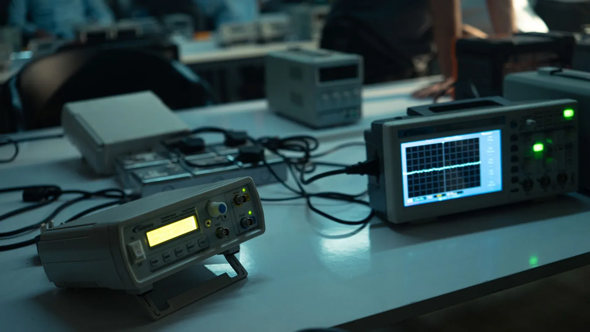
An insulation-resistance reading and a dielectric withstand result are not two ways of reporting the same busbar test. The first produces a resistance value that can support condition assessment or workmanship checks. The second is a controlled proof test: the defined test object must withstand a specified electrical stress under an approved procedure.
Confusing them creates two opposite risks. A factory may accept an assembly because its megohmmeter displayed a large number even though the required withstand test was never performed. Or a maintenance team may apply an unnecessarily severe hipot test to an installed system, stressing connected devices and insulation without a justified test plan.
The Two Tests Answer Different Questions
A megohmmeter applies a DC test voltage and measures the resulting current to calculate resistance. The reading is affected by surface leakage, insulation absorption, capacitance, contamination, moisture, temperature, elapsed test time and the connections included in the test. It is most useful when the method and conditions are recorded so results can be compared.
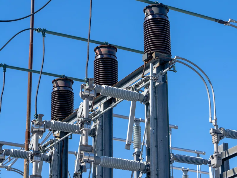
A hipot tester—also called a dielectric withstand tester—applies the voltage, waveform and duration prescribed for the test. The acceptance decision may consider breakdown, flashover, tester trip or leakage behavior defined by the controlling procedure. Megger’s explanation of when to use a hi-pot or a megohmmeter makes the fundamental distinction: the instruments perform different tasks.
Neither result answers every insulation question. Insulation resistance is not a measurement of busbar-joint resistance. Hipot does not establish continuous current rating or acceptable operating temperature. Use the IEC 61439 temperature-rise verification guide for the assembly’s thermal task and the present article only for the electrical-insulation test boundary.
Define the Test Object Before Selecting Voltage
“Test the busbar” is not a sufficient instruction. Identify the physical and electrical object:

- bare conductors supported in an assembly;
- heat-shrink, coated or laminated busbars;
- busway sections and joints;
- low-voltage or medium-voltage switchgear;
- a component before installation or a complete assembly;
- phase-to-phase, phase-to-neutral, or phase-to-ground paths.
Then mark everything connected to those paths. Surge-protective devices, meters, power supplies, instrument transformers, electronic controls, filters and other components may change the result or be damaged by a test they were not designed to receive. Any disconnection, bonding or temporary wiring must be defined, authorized, recorded and restored through a verification step.
The applicable product or assembly standard, equipment manufacturer, approved project specification and test purpose determine the voltage, waveform, duration and acceptance rule. ABB’s technical application paper on IEC 61439 assemblies is useful context for assembly verification, but the purchased standard and the actual assembly documentation remain controlling.
Do not extract a voltage from a table for a different rated system or reuse a factory routine-test value as a maintenance recommendation. Design verification, routine production verification, site acceptance after installation and diagnostic maintenance are different decisions.
Write a Safe Isolation and Discharge Procedure
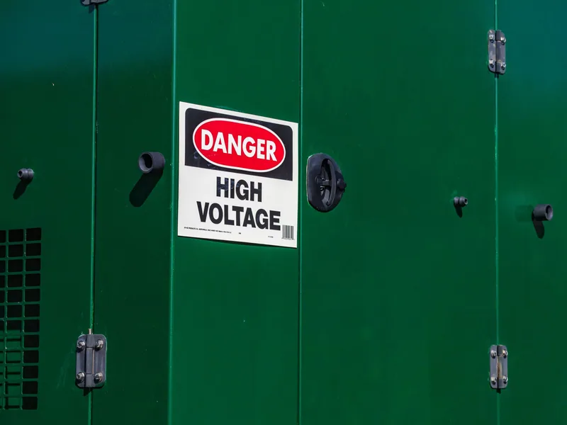
High test voltage and stored charge can injure people after the tester appears to be off. Testing belongs to qualified personnel working under the site’s electrical-safety and energy-control program. The procedure should define at least:
- authorization and test boundaries;
- de-energization, isolation and absence-of-voltage verification;
- discharge, grounding and treatment of induced or stored energy;
- barriers, warning signs and control of access;
- instrument rating, inspection and connection sequence;
- remote operation or observer requirements;
- stop conditions and response to a failed test;
- post-test discharge, verification and reconnection.
Do not handle test leads, move barriers or reconnect equipment until the approved discharge and verification steps are complete. Larger insulated systems and connected capacitive elements can retain energy. The test-set manual specifies how its discharge function is used; the site procedure determines how a safe state is confirmed.
The busbar insulation-methods guide helps identify the construction being tested. It does not authorize an energized test or replace the assembly-specific safety assessment.
Make Insulation-Resistance Results Comparable
The number on the display has little value without its conditions. Megger’s insulation-resistance testing guidance warns that an excessive test voltage can damage the object and emphasizes selecting the test for the equipment.
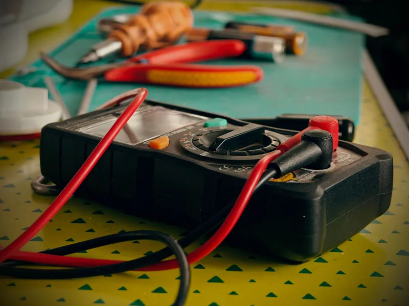
For each reading, retain:
| Record | Why it matters |
|---|---|
| test object and circuit diagram | proves what was—and was not—included |
| connection configuration | distinguishes phase-to-phase and phase-to-ground paths |
| test voltage and elapsed time | prevents unlike readings being compared |
| ambient and object temperature, humidity | helps interpret environmental change |
| surface condition and cleaning | surface leakage can dominate the reading |
| instrument ID and calibration status | supports traceability and measurement confidence |
| raw resistance versus time, when relevant | preserves more information than a single pass label |
| discharge and restoration record | closes the safety and configuration loop |
Trend tests only when the boundary and method are sufficiently consistent. A result taken after washing in humid conditions cannot be compared casually with a dry factory reading. If temperature correction is required, use the method appropriate to the insulation system rather than applying a generic factor.
A very high value may exceed the instrument range. Record it as an over-range result at that range, not as an invented resistance. A low value is a reason to inspect conditions and the test boundary before declaring the insulation defective.
Treat Hipot as a Controlled Proof Test
The approved procedure should state the test voltage source and waveform, ramp behavior, maximum current or trip settings, dwell time, connection sequence, acceptance criteria, and discharge method. It should also identify whether the test is required after a particular repair, modification, transport event or production stage.

Raising voltage slowly can give the operator controlled visibility and avoid an abrupt application, but it does not authorize changing the specified level or duration. Leakage current includes effects from the test object and setup; a universal leakage limit detached from capacitance, configuration, tester and standard is not defensible.
Run the test with the required barriers and instrument controls. Record the actual applied voltage and duration, not merely the programmed target. If the tester trips, flashes over, behaves erratically or produces another fail condition, stop under the procedure. Repeatedly applying the test until the assembly passes can further stress a defect and erase useful evidence.
Build a Record That Survives FAT, Site Work, and Warranty Review
The report should allow another qualified person to reconstruct the test without guessing. Include the assembly identifier and serial number, drawing and schematic revisions, rated characteristics, applicable standard and clause or project procedure, test purpose, date, location and responsible people.

List every disconnected, shorted or temporarily bonded device and confirm restoration. Attach instrument identification, calibration status, connections, settings, raw values, environmental conditions, result, anomaly photographs where permitted, and any deviation approval. Connect the report to the broader finished-busbar inspection record so electrical, material, geometry and coating evidence remain associated with the same product.
At site acceptance, compare the installed configuration with the factory configuration before expecting comparable values. Cable connections, moisture, contamination, field modifications and connected loads can change the test boundary.
Investigate a Failure Without Repeatedly Stressing the Assembly
First preserve the failed configuration and data. Verify that the correct procedure, connection and settings were used. Then inspect for conductive debris, moisture, contaminated surfaces, damaged or pinched insulation, incorrect clearances, sharp edges, misplaced hardware, transport damage and devices that should have been isolated.
Separate the system into approved test sections only if the equipment design and procedure allow it. A lower-voltage insulation-resistance check may help localize a path, but it does not erase the failed withstand test. Repairs must be documented and the retest authorized with a stated scope.
Finally, treat recurring failures as process evidence. If damage is consistently found near a punched edge, bend, fastener or coating transition, feed the result back to fabrication and design—not merely to the test station. The objective is not to make the tester show PASS. It is to prove that the defined assembly was built, tested and restored under controlled conditions.
Frequently Asked Questions (FAQs)
What is the difference between an insulation-resistance test and a hipot test?
An insulation-resistance test measures resistance under a stated DC voltage, time, temperature, humidity, and connection. A hipot or dielectric withstand test applies a specified high voltage to demonstrate that the test object withstands the prescribed stress without breakdown or an unacceptable response.
Can every busbar assembly use the same insulation test voltage?
No. Voltage, waveform, duration, connection, acceptance criterion, and treatment of connected devices depend on the assembly type, rated characteristics, applicable standard, manufacturer instructions, project specification, and whether the test is for design, routine production, acceptance, or maintenance.
Why must a busbar assembly be discharged after an insulation test?
Insulated conductors and connected components can store electrical energy during a DC or high-voltage test. The approved procedure must remove and verify that stored charge before the test object is touched, reconnected, or returned to service.
Does a high insulation-resistance value guarantee that a busbar will pass a hipot test?
No. The tests stress and evaluate the insulation differently. A high resistance reading does not prove adequate clearance, withstand strength, workmanship, or freedom from a localized defect under the specified dielectric test.