
Busbar Infrared Thermography: A 2026 NFPA 70B Inspection Workflow
As of August 31, 2026, the current NFPA 70B edition is the 2026 Standard for Electrical Equipment Maintenance. A thermography route should sit inside the facility’s electrical maintenance program, equipment-condition assessment and safety procedures—not exist as a folder of colorful images collected once a year.
For busbars, repeatability is especially important. Bare copper is reflective, operating load changes heat generation, airflow changes cooling, and a camera can display a precise-looking temperature even when the surface assumptions are poor. A credible inspection therefore records how the image was obtained and what operating condition it represents.
Use the 2026 Standard Inside an Electrical Maintenance Program
The site should review its licensed copy of NFPA 70B 2026, applicable regulations, manufacturer instructions and adopted maintenance policy. These sources determine the equipment scope, condition assessment, maintenance intervals, personnel qualifications, records and response requirements. A website summary cannot decide compliance for a specific facility.
Build the thermography route from the asset register. Identify switchgear, busway, panels, joints, disconnects and other current-carrying connections that require inspection. Associate each location with equipment condition, criticality, previous anomalies, manufacturer access provisions and the safe method of obtaining line of sight.
The route must also define what happens after a finding. A temperature image without a priority rule, owner, due date and closure evidence is observation—not maintenance.
Keep thermography separate from two related tasks. The busbar contact-resistance guide covers the physics and low-resistance measurement of joints. The IEC 61439 temperature-rise article covers assembly design verification under a controlled test. Online infrared inspection screens installed equipment under its operating condition; it does not replace either one.
Plan the Scan Before Energized Work Begins
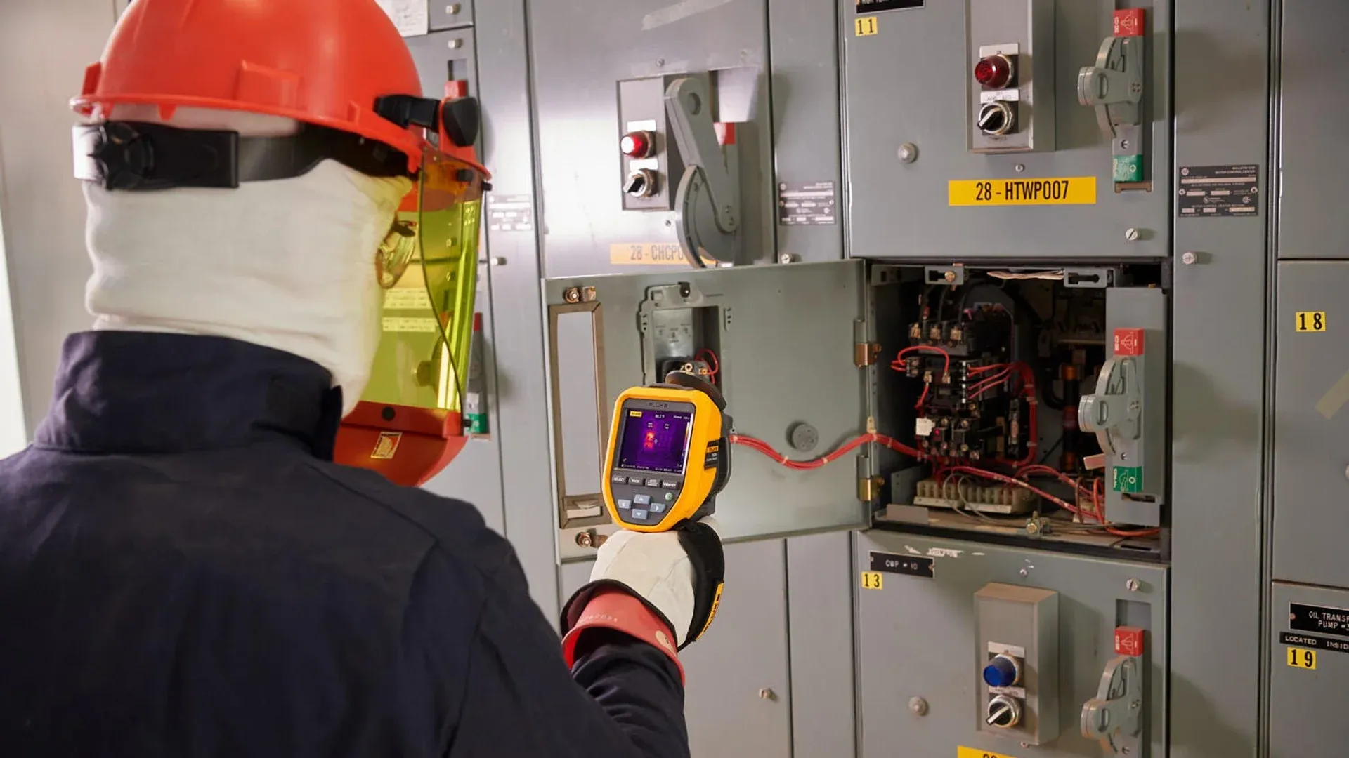
Only qualified people working under the facility’s electrical-safety program should inspect energized equipment. Complete the shock and arc-flash risk assessment, establish approach boundaries and PPE, and follow the authorized operating and access procedure. Never remove a cover simply to improve an image unless the task and hazard controls permit it.
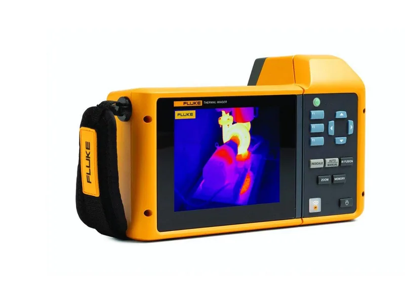
Where the equipment design and risk assessment support them, infrared windows can provide a repeatable line of sight without opening an energized enclosure. Their material, location, field of view, transmission and maintenance must be included in the camera setup. A window is not transparent to every infrared wavelength and does not eliminate the need for qualified work.
For every route point, define:
- asset and connection identifier;
- camera position, distance and viewing angle;
- whether a window or other access provision is used;
- expected operating state and load window;
- comparable reference points;
- required visible-light and thermal images;
- data fields and anomaly escalation rule.
Use the same route and labels in later inspections. If an inspector cannot find the same joint or views it from the opposite side, the trend loses value.
Record Operating Conditions With Every Thermogram
Electrical heating is related to current and resistance, while measured surface temperature also reflects heat transfer. A thermogram taken at light load cannot be compared casually with one taken during peak production.
Attach the following to each finding:
| Field | Purpose |
|---|---|
| phase currents or suitable load measure | distinguishes connection heating from different loading |
| percentage of normal/rated load where known | supports comparison and severity review |
| load stability and operating mode | identifies a transient or unusual process state |
| ambient temperature and relevant airflow | explains changes in cooling |
| camera, lens, calibration status and settings | preserves measurement traceability |
| distance, angle, focus and target | helps reproduce the image |
| emissivity and reflected-temperature method | exposes assumptions behind radiometric values |
| reference component or area | supports like-for-like temperature difference |
| time, asset ID and inspector | connects the image to the maintenance record |
Do not rely on a maximum-temperature marker that can jump to a reflected object, background opening or adjacent hot part. Set the measurement area on the intended target and retain the raw radiometric image where the workflow permits it.
Treat Bare Copper as a Difficult Measurement Surface
Fluke’s discussion of thermography on reflective surfaces explains why low-emissivity metal can reflect its surroundings and produce unreliable apparent temperatures. Clean copper is particularly difficult. Surface oxidation, plating, roughness and viewing angle can all change the effective emissivity.
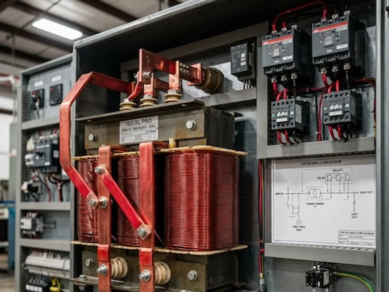
The August 2026 FLIR article on thermography mistakes and copper busbars demonstrates how direct measurement on reflective copper can severely understate a temperature difference compared with an appropriate high-emissivity target.
If the maintenance program uses a high-emissivity patch, coating or label, it should be compatible with the voltage, temperature, material, environment and equipment listing. Install it during an approved de-energized work condition—not by reaching into live equipment with a roll of tape. Record the target material and camera setting and keep the target location consistent.
When no qualified target exists, emphasize qualitative patterns and comparable surfaces and state the measurement limitation. A precise camera display does not make an uncertain emissivity assumption precise.
Compare Like With Like Before Assigning Severity
Start with equivalent phases, parallel conductors, identical joints or repeated devices under comparable loading. Look at the thermal pattern, not only the hottest pixel. A resistive connection often concentrates heating around the interface and then conducts heat away. An overload or cooling problem may warm a longer conductor or several components. Those are clues, not diagnoses.
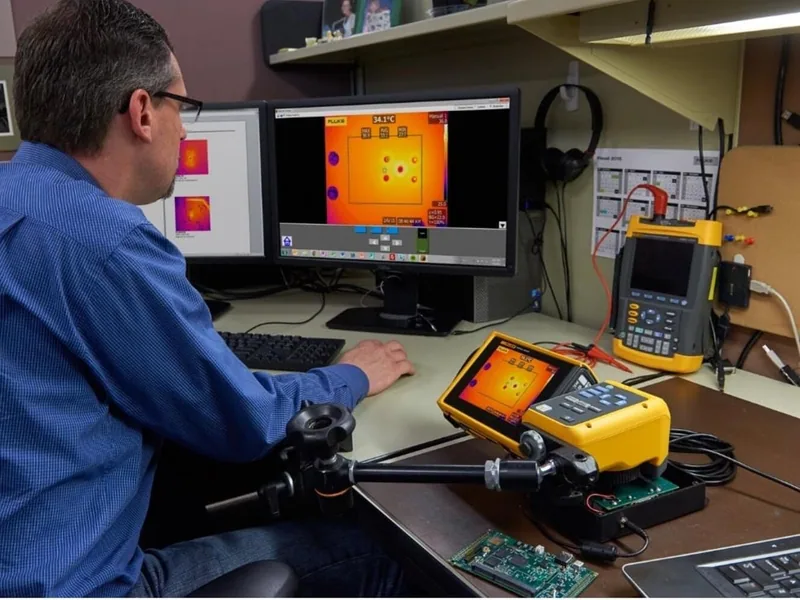
Compare with the same asset’s earlier images under similar conditions. Track whether the anomaly grows, remains stable or changes with load. Account for different finishes: a tinned contact, painted enclosure and bare copper bar can display different apparent temperatures even when physically equal.
Avoid a universal “Delta T equals action” rule detached from the applicable standard, equipment, reference method and site risk. The work-order priority should consider the approved temperature criteria, load, component rating, equipment condition, criticality, trend, measurement confidence and consequence of failure.
Translate a Pattern Into an Investigation, Not a Diagnosis
An abnormal pattern can be associated with a loose or degraded joint, contamination, plating damage, inadequate contact pressure, overload, imbalance, harmonic current, failed cooling, adjacent heat source or measurement artifact. Open a work order that states the observed pattern and conditions rather than asserting an unverified cause.
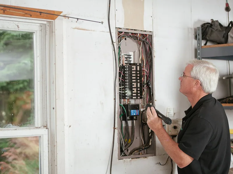
Select confirmation steps through the maintenance and safety procedure. They may include load measurement, visual inspection after de-energization, hardware and contact examination, torque-procedure review, a qualified low-resistance measurement, insulation checks or other equipment-specific tests. Do not retighten an energized joint or apply a torque wrench blindly to a plated connection.
If the anomaly is associated with physical deformation, damaged support or signs of a short-circuit event, include the mechanical checks described in the busbar short-circuit and support-spacing guide.
Close the Work Order With a Repeatable Post-Repair Scan
Document the de-energized inspection, confirmed cause, parts and surfaces affected, repair method, hardware replacement, approved tightening procedure and any electrical test. Update the equipment-condition assessment and route if the finding changes risk or inspection frequency.
After return to service, repeat the thermal view at a suitable and sufficiently comparable load. Use the same camera position, target and settings where possible. Record differences in current, ambient and cooling rather than claiming an exact before/after improvement from unlike conditions.
The closure decision should be explicit: corrected and verified, acceptable for continued monitoring under a stated interval, further engineering required, or removed from service under the site’s rule. Retain both the original and post-repair records.
Thermography is powerful because it sees operating equipment without interrupting the current path. Its value depends on disciplined context. Control line of sight, load, emissivity, references and follow-through, and a busbar image becomes maintenance evidence rather than a persuasive but ambiguous picture.
Frequently Asked Questions (FAQs)
Why is bare copper difficult to measure with a thermal camera?
Clean or polished copper has low emissivity and high reflectivity, so the camera can receive substantial infrared energy reflected from the surroundings. The apparent temperature can be misleading unless surface, reflected temperature, angle, focus, camera settings, and an approved measurement method are controlled.
Does a busbar hot spot prove that a bolted joint is loose?
No. A thermal pattern is evidence for investigation, not a root-cause proof. Increased contact resistance is one possibility, but overload, phase imbalance, harmonics, cooling, adjacent heat, measurement reflection, or another defect can produce a warm pattern.
What load information should be recorded during busbar thermography?
Record phase currents or another suitable load measure, percentage of rated or normal load when available, load stability, ambient conditions, airflow, equipment state, and the time associated with the thermogram. Comparable load is essential for trending.
Should a busbar be scanned again after a repair?
Yes. A controlled post-repair scan under a comparable operating condition helps verify that the thermal anomaly changed as intended. It should be combined with the inspections or electrical tests required by the repair and maintenance procedure.