
How Does 800V EV Architecture Change Busbar Design Requirements in 2026?
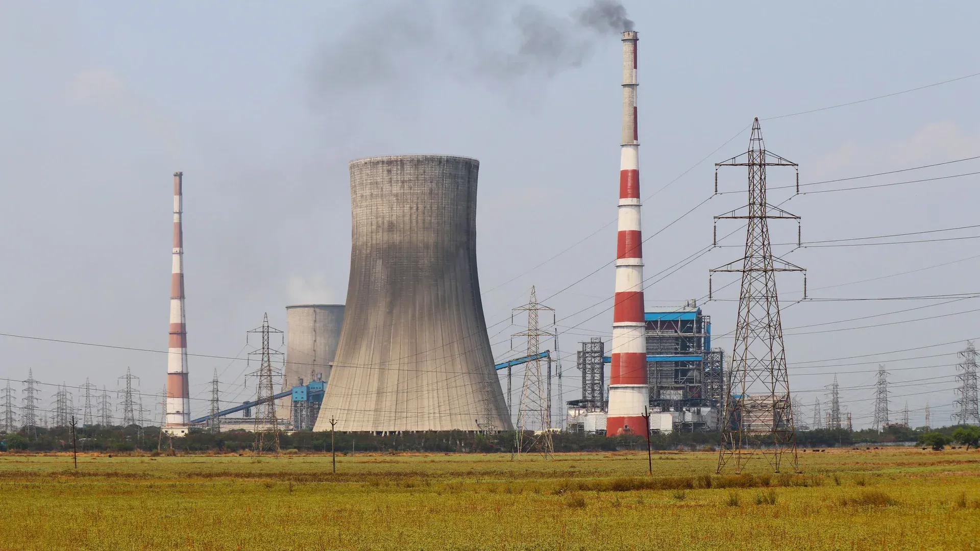
At DH CNC, our engineering team in Jinan has observed a fundamental shift in busbar design workflows since 2023: the transition from 400V to 800V EV architectures is not simply a matter of increasing insulation thickness. It demands a complete rethinking of conductor geometry, edge conditioning, and inter-layer relationships. IEC 60664-1 mandates a minimum creepage of 4.0mm for 800V DC at Pollution Degree 2, while corona discharge inception voltage drops to as low as 1.1kV peak on conductors with burred edges below 0.1mm radius, per research published in the IEEE Transactions on Power Electronics (2024). A properly designed 800V laminated busbar targets inductance below 15nH to protect SiC MOSFETs from voltage overshoot during 50kV/μs switching transients. With the global 800V EV market projected to grow from $4.28B in 2024 to $24.41B by 2032 (Fortune Business Insights, 2025), these design parameters are no longer academic — they are production-floor requirements that separate qualified Tier-1 suppliers from the rest.
Why Does 800V Architecture Fundamentally Change Busbar Creepage and Clearance Requirements?
The shift from 400V to 800V doubles the DC link voltage, but the design impact on busbar insulation coordination is non-linear. Under IEC 60664-1:2020, the creepage distance required for basic insulation increases from 2.5mm at 400V to 4.0mm at 800V for Pollution Degree 2 — a 60% increase, not a simple doubling. This is because the standard’s creepage tables follow an approximately square-root relationship with voltage, reflecting the physics of surface tracking.
Clearance requirements follow a different curve entirely. For reinforced insulation at 800V DC with an overvoltage category of II, the minimum clearance through air is 4.2mm at sea level. However, at 3,000m altitude — relevant for EVs operating in high-elevation markets — that clearance must be derated by a factor of 1.45 per IEC 60664-1 Table A.2, yielding a design clearance of 6.1mm. This is a dimension that directly impacts the form factor of an EV inverter busbar assembly.
At our factory, when we machine busbars for 800V traction inverter applications, we apply the following design rules as a starting point:
| Design Parameter | 400V System (Reference) | 800V System | Derating Factor / Standard |
|---|---|---|---|
| Minimum creepage (bare Cu, PD2) | 2.5 mm | 4.0 mm | IEC 60664-1 Table F.2 |
| Minimum clearance (reinforced, sea level) | 2.8 mm | 4.2 mm | IEC 60664-1 Table F.1 |
| Clearance at 3,000m altitude | 3.5 mm | 6.1 mm | IEC 60664-1 Table A.2 (×1.45) |
| Comparative Tracking Index (CTI) required | ≥400 (Group II) | ≥600 (Group I) | IEC 60112 |
| Typical inter-phase air gap | 4-5 mm | 6-8 mm | DH CNC engineering guideline |
What this table does not capture is the compounding effect: higher voltage increases both the dielectric stress and the consequence of any localized defect. A 0.05mm burr on a 400V busbar edge is a quality escape. The same burr on an 800V busbar is a field-failure mechanism.
How Does Corona Discharge Physics Dictate Busbar Edge Quality Requirements?
Corona discharge — partial breakdown of air around a conductor at voltage stress concentrations — becomes a first-order design concern at 800V. The physics is straightforward: the electric field strength E at the surface of a conductor is inversely proportional to the radius of curvature r. A sharp edge with r=0.02mm produces an approximate field enhancement factor of 50-100x compared to a flat surface, meaning the local field can exceed the 3kV/mm dielectric strength of air even when the nominal applied voltage is well below breakdown.
For an 800V DC busbar, the peak operating voltage including ripple can reach approximately 880V. With a sharp edge (r<0.05mm), localized field strengths can exceed 2.5kV/mm — above the partial discharge inception threshold. The failure mode is insidious: low-level corona does not cause immediate catastrophic failure, but it generates ozone and nitrogen oxides that chemically attack the polyimide or Nomex insulation layers over months of operation, eventually leading to tracking and a dead short.
At DH CNC, we specify the following edge conditioning requirements for 800V busbars processed through our CNC busbar bending center:
| Edge Quality Parameter | Standard Switchgear Busbar | 800V EV Busbar | Measurement Method |
|---|---|---|---|
| Minimum edge radius | 0.3 mm | 1.0 mm | Profile projector (20x magnification) |
| Maximum burr height | 0.1 mm | 0.05 mm | Digital micrometer, 3 points per edge |
| Surface roughness (Ra) on cut edges | 6.3 μm | 3.2 μm | Contact profilometer |
| Edge chamfer tolerance | Not specified | 45° ±2°, consistent along length | Optical comparator |
| Post-machining treatment | Optional | Mandatory electropolishing or vibratory deburring | Visual inspection at 10x |
I have seen a European Tier-1 customer reject an entire shipment because the busbar edges, although within the 0.1mm burr specification on the drawing, showed inconsistent edge rounding under SEM inspection. At 800V, the margin between “passes dimensional check” and “survives 8,000-hour life test” is narrower than many procurement teams realize.
External reference: Zhu et al. (2024), “Partial Discharge Characteristics of Busbar Insulation Systems Under PWM Excitation,” IEEE Transactions on Power Electronics, vol. 39, no. 3, documents PDIV degradation from 2.1kV to 1.1kV on conductors with burr heights exceeding 0.08mm in 800V SiC inverter applications.
What Makes Laminated Busbar Design Critical for Low Inductance in 800V Inverters?
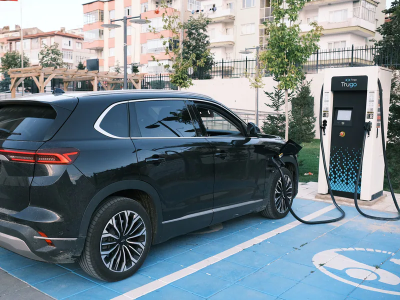
Stray inductance in the DC link busbar is the enemy of every 800V traction inverter designer. The reason is switching speed. SiC MOSFETs — now dominant in 800V platforms from the Hyundai E-GMP to the Lucid Air drivetrain — switch at dv/dt rates exceeding 50kV/μs. The voltage overshoot during turn-off is governed by:
V_overshoot = L_stray x (di/dt)
With SiC di/dt values routinely reaching 10-20A/ns, even 20nH of stray inductance generates a 200-400V overshoot on top of the 800V DC bus. This overshoot eats directly into the voltage margin of 1,200V-rated SiC devices, and if total V_ds exceeds 1,200V, avalanche breakdown destroys the module.
This is where laminated busbar design becomes non-negotiable. A laminated busbar sandwiches positive and negative DC conductors with a thin dielectric layer — typically 0.2-0.5mm of high-temperature polyimide or epoxy-glass prepreg — creating a transmission-line structure where the opposing current paths generate canceling magnetic fields.
The inductance of a parallel-plate busbar is approximated by:
L ≈ (μ₀ x l x d) / w
Where l is the conductor length, d is the dielectric thickness, and w is the conductor width. Reducing dielectric thickness from 0.5mm to 0.2mm cuts inductance by 60%. Increasing conductor width from 40mm to 80mm halves it. This is why 800V inverter busbars are trending toward wide, thin laminations — a geometry that demands precision flatness.
At DH CNC, when we support customers designing for EV busbar and new energy applications, our multi-function busbar processing center achieves the flatness and positional accuracy required for multi-layer lamination:
| Lamination Parameter | Standard Flat Busbar | Optimized 800V Laminated Busbar |
|---|---|---|
| Dielectric thickness | 0.25-0.50 mm | 0.12-0.20 mm |
| Conductor flatness over 300mm | 0.5 mm | 0.15 mm |
| Layer-to-layer alignment tolerance | ±0.3 mm | ±0.15 mm |
| Target stray inductance | 30-50 nH | 8-15 nH |
| Partial discharge inception voltage | >1.5 kV | >2.5 kV |
| Thermal resistance (junction-to-coolant) | ~0.15 K/W | ~0.08 K/W |
External reference: The relationship between dielectric thickness and stray inductance in laminated busbars is well-characterized in Caponet et al. (2002), “Low Stray Inductance Bus Bar Design and Construction for SiC-Based Inverters,” IEEE Transactions on Industry Applications, which established the parallel-plate inductance model still used in industry design tools today.
How Do Thermal Profiles Differ Between 400V and 800V Busbar Systems?
A common misconception is that 800V systems run cooler because current is halved. The reality is more nuanced. While I²R losses in the busbar conductor do decrease — 312.5A in an 800V system vs 625A in a 400V equivalent produces approximately 75% less resistive heating for the same conductor cross-section — the heat sources in an 800V inverter are concentrated differently:

-
Dielectric heating increases. The AC component of the DC link ripple current, which flows through the busbar capacitance at the PWM switching frequency, generates dielectric losses proportional to V² x f x C x tanδ. Doubling voltage quadruples these losses.
-
Proximity effect intensifies. In laminated busbars, the AC ripple current concentrates at conductor edges closest to the return path. At 800V, the di/dt is higher due to faster SiC switching, increasing the effective AC resistance of the busbar even though the DC current is lower.
-
Hot-spot concentration. The thermal time constants of the thin dielectric layers (milliseconds) are far shorter than the copper conductors (seconds to minutes), meaning transient thermal gradients across the lamination stack can exceed 30°C during peak load.
For these reasons, our engineering team recommends the following thermal design margins for 800V busbar systems:
| Thermal Parameter | 400V Design Guideline | 800V Design Guideline |
|---|---|---|
| Max continuous conductor temperature | 105°C (Class A insulation) | 130°C (Class B minimum) |
| Dielectric max operating temperature | 130°C (PET) | 180°C (polyimide) or 220°C (Nomex 410) |
| Hot-spot allowance above rated T | +15°C | +10°C (tighter margin due to voltage de-rating) |
| Temperature rise test duration (IEC) | 8 hours to steady state | 8 hours + 30% margin check at 960V DC |
| Thermocouple placement requirement | 3 points per phase | 6 points per phase, including dielectric interface |
External reference: Luckose et al. (2023), “Thermal Management of Laminated Busbars for 800-V Inverters Using SiC MOSFETs,” SAE Technical Paper 2023-01-0987, provides experimental data showing up to 22°C temperature difference between conductor center and dielectric interface in 800V laminated busbars under 250kW load cycling.
Why Does ±0.2mm Bending Precision Matter Specifically at 800V?
When I speak with procurement engineers who have previously sourced busbars for 400V switchgear applications, the most common pushback I hear is: “We have been accepting ±0.5mm tolerance for years — why does 800V require ±0.2mm?”

The answer lies in partial discharge physics, not mechanical fit. Partial discharge inception voltage is a function of the local electric field, which depends on the minimum gap distance between conductors at any point along their surfaces. In a multi-phase busbar assembly, a 0.5mm deviation on one conductor combined with a 0.5mm deviation in the opposite direction on the adjacent conductor results in a 1.0mm gap reduction at the worst-case location.
At an 800V DC operating point with a design air gap of 6mm, a 1mm reduction to 5mm increases the nominal field strength by 20%. More critically, if that same location also has an edge radius defect, the combined effect can push the local field above the PDIV threshold. This is why we treat precision as a safety parameter, not just a quality metric.
Our CNC busbar punching and shearing machine and bending centers are calibrated to deliver:
- Bend angle repeatability: ±0.2° across production runs of 1,000+ pieces
- Bend center positional accuracy: ±0.15mm
- Twist and bow across 500mm length: ≤0.3mm
- Hole position accuracy: ±0.05mm (critical for capacitor mounting in laminated stacks)
External reference: Montanari et al. (2021), “Partial Discharges in Insulation Systems for Power Electronics: Phenomenology, Detection, and Life Modeling,” IEEE Electrical Insulation Magazine, vol. 37, no. 4, demonstrates through accelerated life testing that a 20% reduction in design air gap correlates to approximately 60% reduction in insulation life at 800V DC PWM waveforms.
How Does Material Thickness Selection Change for 800V vs 400V Busbars?
The voltage doubling from 400V to 800V creates an apparent paradox in material thickness selection. On one hand, halving the current for equivalent power reduces the required cross-sectional area. On the other hand, the structural demands of maintaining precise inter-conductor gaps over the vehicle’s vibration life require a minimum stiffness that often sets the lower bound on thickness.
Let me walk through a real design comparison for a 250kW traction inverter application:
400V System Design:
- DC link current: 625A (250kW / 400V)
- Required cross-section (at 4A/mm² design rule): 156mm²
- Selected conductor: 80mm wide x 8mm thick (two per polarity) = 1,280mm² total
- Weight per busbar set: approximately 5.7kg (copper)
- Thermal margin above design ambient: 25°C
800V System Design:
- DC link current: 312.5A (250kW / 800V)
- Required cross-section (at 4A/mm²): 78mm²
- Selected conductor: 80mm wide x 3mm thick (single per polarity) = 240mm²
- Weight per busbar set: approximately 2.1kg (copper)
- Thermal margin: 18°C
At first glance, the 800V design saves 63% on copper weight — a meaningful figure when LME copper is trading at $10,000-13,500/ton (LME, June 2026). But the 3mm conductor introduces a problem: flatness. A 3mm x 80mm x 400mm copper bar has a significantly lower section modulus than an 8mm bar, making it more prone to bowing during the lamination pressing process. If the bar bows 0.3mm out of plane across a 400mm span, it can locally compress the dielectric layer by 0.3mm — a 60% reduction if the nominal dielectric is 0.5mm thick, creating a voltage stress concentration.
Our practical recommendation for 800V EV busbars is:
| Conductor Width | Minimum Thickness (Mechanical) | Minimum Thickness (Electrical) | Recommended Thickness |
|---|---|---|---|
| 40 mm | 2.0 mm | 1.5 mm | 2.5 mm |
| 60 mm | 2.5 mm | 2.0 mm | 3.0 mm |
| 80 mm | 3.0 mm | 2.5 mm | 4.0 mm |
| 100 mm | 4.0 mm | 3.0 mm | 5.0 mm |
The “Recommended Thickness” column represents what we have found to be the practical minimum for maintaining flatness through the lamination, bending, and vehicle-vibration lifecycle. Going below these values is possible with additional stiffening ribs in the busbar geometry, but the cost of the added forming operation often negates the material savings.
External reference: LME official copper cash settlement prices averaged $11,282/ton in Q2 2026 (London Metal Exchange, June 2026). For busbar-grade ETP copper (C11000) with 100% IACS minimum conductivity certification, expect a 15-20% premium over LME cash price from qualified mill suppliers.
What Real Design Specifications Do Tier-1 EV Battery Pack Busbars Follow?
To ground this discussion, here are anonymized design specifications drawn from actual Tier-1 EV battery pack busbar projects we have supported at DH CNC. These are not theoretical exercises — they represent the engineering parameters that passed OEM PPAP (Production Part Approval Process) validation for 800V platforms in 2024-2026.
Battery Module Interconnect Busbar (800V Pack)
| Specification | Value | Standard / Rationale |
|---|---|---|
| Material | C11000 ETP Copper, 1/2 hard (H02) | 100% IACS minimum, stable springback |
| Nominal thickness | 2.0 mm | Optimized for weight vs flatness |
| Nickel plating | 3-5 μm electroless nickel, 1-2 μm flash tin overplate | Corrosion resistance + low contact resistance |
| Insulation | 0.25mm Nomex 410 paper, pressure-sensitive adhesive backing | 220°C thermal class, UL 94 V-0 |
| Creepage distance (coated) | 3.2 mm minimum | IEC 60664-1 PD1 equivalent with conformal coating |
| Bend angle tolerance | 90° ±0.3° | Stress relaxation compensation included |
| Flatness across 250mm span | ≤0.2 mm | Measured on granite surface plate |
| Partial discharge test | <10pC at 1.2kV AC (60s hold) | IEC 60270 |
| Hi-pot test | 2.5kV DC, 60s, leakage <1mA | Per OEM specification |
| Operating temperature range | -40°C to +150°C | Automotive AEC-Q200 thermal cycling |
These specifications are achievable with the right equipment and process controls. The challenge for sourcing teams is that not every CNC busbar machine on the market can consistently hold these tolerances across production volumes. When you are manufacturing 500,000 busbars per year for a single EV platform, a 0.1% fallout rate still means 500 field failures — which in an 800V battery pack can mean thermal runaway.
For buyers evaluating suppliers, I recommend reviewing our guidance on how to verify and audit a CNC busbar machine factory in China before placing production orders. The difference between a supplier who understands 800V design requirements and one who is simply “machining copper to a drawing” becomes apparent within the first 15 minutes of a technical audit.
External reference: The IATF 16949:2016 standard, mandatory for Tier-1 automotive suppliers, requires documented process capability studies (Ppk ≥1.67 for safety-critical characteristics). For 800V busbars, we classify creepage distance, edge radius, and inter-layer alignment as safety-critical characteristics requiring full SPC (Statistical Process Control) monitoring throughout production.
How Should Procurement Teams Evaluate 800V Busbar Manufacturing Capability?
After more than a decade of supplying busbar processing equipment to manufacturers across 30+ countries, I have developed a short technical evaluation framework that cuts through sales presentations and gets to the engineering reality. When a factory claims 800V busbar capability, here is what I tell our customers to verify:
1. Edge Conditioning Equipment
Ask to see the deburring or edge radiusing process in operation. A factory doing 800V busbars should be running either an electropolishing line or a vibratory finishing system with documented process parameters, not relying on manual deburring with abrasive pads. Ask what edge radius they guarantee and how they measure it.
2. Partial Discharge Testing Capability
If they cannot perform PD testing per IEC 60270 in-house, they are not qualified to ship 800V EV busbars. Period. PD testing is not something you subcontract — it is the final gate that confirms your entire manufacturing process has produced a busbar free of the microscopic defects that cause field failures.
3. Flatness Measurement Protocol
A granite surface plate, a dial indicator on a height gauge, and a documented measurement grid. If they measure flatness with a caliper at one point and call it good, walk away.
4. Material Traceability
For 800V EV applications, each busbar must be traceable to a material heat number and plating batch. The IATF 16949 requirement for forward/backward traceability applies to busbars just as strictly as it applies to the power modules they connect.
For manufacturers looking to bring 800V busbar production in-house or qualify a new supplier, our engineering team provides custom solution consulting that includes process capability studies, tooling qualification, and first-article inspection support. We also welcome technical discussions through our request a consultation page — no purchase commitment required.
What Is the Total Cost Picture for 800V Busbar Production in 2026?
The economic equation for 800V busbar manufacturing has shifted meaningfully in 2026. Let me break down the cost drivers as we see them from the equipment and process side:
Raw Material Costs: As noted, LME copper at $10,000-13,500/ton means a single 250kW inverter busbar set at 2.1kg represents approximately $25-30 in raw copper. The nickel-tin plating adds roughly $3-5 per busbar set at production volumes above 100,000 units/year.
Processing Cost: The precision requirements at 800V add approximately 35-50% to the per-part processing cost compared to equivalent switchgear busbars. This comes from:
- Slower bending speeds to maintain ±0.2° tolerance
- Mandatory post-machining edge conditioning
- 100% dimensional inspection on critical characteristics
- PD testing on a sampling basis (typically 1 per 100 pieces for production, 100% for PPAP)
Tariff Impact: For buyers importing busbars or busbar processing equipment from China, the Section 301 tariffs remain at 25% on most CNC machinery (HTS 8462.21) and fabricated copper busbars (HTS 7419.80) as of July 2026. The Biden administration’s extension maintains these rates with no sunset date. However, the Section 301 exclusion process remains available for categories where domestic production capacity is insufficient — worth checking with your customs broker before assuming the full 25% applies.
Total Landed Cost Estimate (busbar set for 250kW 800V inverter):
| Cost Component | Per-Unit Cost (10k volume) | Per-Unit Cost (100k volume) |
|---|---|---|
| Copper (C11000, 2.1kg) | $28.00 | $24.00 |
| Nickel-tin plating | $5.00 | $3.50 |
| Insulation material (Nomex 410) | $4.00 | $2.80 |
| CNC processing (bend, punch, form) | $12.00 | $8.00 |
| Edge conditioning | $3.50 | $2.00 |
| Quality assurance (PD test, dimensional) | $4.00 | $2.50 |
| Section 301 tariff (25% on landed cost) | $14.13 | $10.70 |
| Freight and logistics | $3.50 | $2.20 |
| Total landed per busbar set | $74.13 | $55.70 |
These figures explain why many global manufacturers are investing in in-house busbar production capacity. The payback period for a $60,000-$180,000 CNC busbar processing system — depending on automation level — is typically 18-24 months at 50,000+ units per year, driven primarily by tariff savings and quality control benefits rather than labor cost differential.
For connection design beyond rigid EV bars, see our flexible busbar selection guide for foil, braid and laminated connections. Engineers managing switching-loop inductance can continue with the laminated busbar design and manufacturing guide.
Frequently Asked Questions (FAQs)
What is the minimum creepage distance for an 800V DC busbar per IEC 60664-1?
For 800V DC at Pollution Degree 2 (typical EV inverter enclosure), IEC 60664-1 requires a minimum creepage distance of 4.0mm for uncoated conductors. With conformal coating applied, this can be reduced to approximately 1.6mm using the protection factor for Pollution Degree 1 equivalent conditions. At DH CNC, we recommend 4.5mm minimum on bare copper busbars for production margin, as field contamination can degrade the effective creepage path over the vehicle's 15-year service life.
How does 800V architecture affect busbar material thickness compared to 400V systems?
Contrary to what many engineers initially assume, 800V systems often allow thinner busbars than equivalent-power 400V systems. Because P = V x I, doubling voltage halves the current for the same power output. A 250kW 400V inverter carries 625A requiring an 80mm x 8mm busbar, while a 250kW 800V inverter at 312.5A can use a 60mm x 5mm section with equivalent temperature rise. However, the voltage stress demands tighter edge rounding (R≥1.0mm) and wider creepage slots, which partially offset the material savings.
What CNC bending precision is required to prevent partial discharge in 800V busbars?
Partial discharge inception voltage (PDIV) drops sharply when adjacent busbar conductors are closer than designed. For 800V DC systems, we specify ±0.2mm bending angle tolerance and ±0.15mm positional accuracy on bend centers. This ensures that the designed air gap — typically 6-8mm between phases in an 800V laminated stack — is maintained across the full conductor length, preventing the localized field concentrations that trigger partial discharge events above 1.5kV/mm in air at standard atmospheric pressure.
DHAC-BB-H Servo-Hydraulic Busbar Bender
Discover details, parameters, standard dies packages, and factory quotes.