
PV Ribbon vs Busbar CNC Machines: What Solar Plants Need

“PV busbar machine” is not one equipment category. Search results combine machines for micrometre-scale coated ribbon with CNC machines for millimetre-scale rigid copper bars. Those processes are not interchangeable, and choosing from the wrong category can produce an unusable line.
Before comparing speed or tolerance, identify which conductor the project will manufacture: cell ribbon, a junction-box connection, or a rigid busbar in power-conversion equipment. DH CNC equipment belongs to the third category. It is not a photovoltaic ribbon drawing, rolling or tinning line.
Three solar conductor families use different machines
| Conductor | Typical manufacturing process | Equipment category |
|---|---|---|
| Cell interconnect or collector ribbon | Drawing/rolling, annealing, cleaning, coating, tension control, winding | Continuous PV ribbon line |
| Thin formed junction-box conductor | Reel feed, straightening, cut-to-length, forming, terminal process | Dedicated cut-and-form equipment |
| Inverter, combiner, switchgear or BESS busbar | Cut, punch, slot, deburr and bend rigid copper or aluminum bar | Busbar CNC punch/shear/bender |
The names “busbar ribbon” and “busbar” refer to electrical function, not equal material thickness or compatible machinery. A ribbon line controls strip tension and coating continuously. A rigid-bar machine clamps a discrete workpiece and applies punching, shearing or bending force.
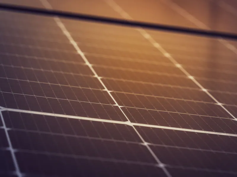
Ribbon production is a continuous metallurgical process
A ribbon project should begin with the module manufacturer’s approved conductor drawing and soldering process. Required equipment can include wire drawing or precision rolling, intermediate and final annealing, surface preparation, flux control, hot-dip or electroplating, cooling, in-line dimensional measurement, tension control, spooling and defect inspection.
Do not copy a generic web specification such as “0.20–0.50 mm × 3–6 mm” into an RFQ without tying it to a qualified module design. Multi-busbar, shingled, back-contact and busbar-free cell architectures use different conductor geometries and joining methods. The line must hold the drawing across production speed, spool transitions and coating changes—not only during a slow demonstration.
Useful acceptance characteristics include:
- incoming copper grade and conductivity;
- width, thickness, camber and edge condition;
- yield or tensile properties after annealing;
- coating material, total coating thickness and uniformity;
- solderability and wetting test method;
- spool geometry, winding tension and allowable defects;
- resistance measurement at a stated temperature;
- capability data at the contracted line speed.
Check resistance claims against conductor geometry
Electrical resistance per metre can be screened with R = ρL/A. Using copper resistivity of approximately 1.68 × 10⁻⁸ Ω·m at 20 °C, a 0.5 × 6 mm conductor has 3 mm² cross-sectional area and an ideal resistance of about 0.0056 Ω/m. A 0.1 × 1.5 mm conductor is about 0.112 Ω/m.
That means a blanket requirement below 0.003 Ω/m is physically inconsistent with the stated 0.1–0.5 mm by 1.5–6 mm range. If a supplier quotes such a value, ask for the test length, temperature, conductor dimensions, measurement uncertainty and whether the unit is actually milliohms per a different length.
Junction-box conductors require a separate forming study
Junction-box connections may be supplied from a coil and cut or formed automatically, but their process still differs from heavy copper busbar machining. Confirm stock thickness, minimum bend radius, cut-length tolerance, terminal geometry, coating protection, feeder compatibility and part collection method.
The applicable product context also matters. IEC 62790:2020 defines safety requirements and tests for junction boxes up to 1,500 V DC used on photovoltaic modules. It does not prescribe one universal machine tolerance or certify the forming line. The junction-box manufacturer must qualify the final construction and control the conductor process that supports it.

Heavy PV power electronics use rigid busbar CNC equipment
Utility inverters, combiner cabinets, transformer interfaces and battery-energy-storage systems contain rigid copper or aluminum conductors. These are the solar applications served by conventional busbar processing equipment.
For example, the DHCNC-BP-60 punching and shearing workstation is published for bars up to 200 × 15 mm, with a 3 mm minimum thickness listed in its working range. The DHAC-BB-H bending machine is a dedicated 400 kN bender for formed rigid bars. Neither specification describes 0.1–0.5 mm PV ribbon production.
The practical production flow for rigid solar-power busbars is normally:
- cut and punch the rigid conductor;
- deburr and clean contact areas;
- bend where the enclosure layout requires it;
- apply the specified surface treatment or insulation;
- inspect dimensions and contact surfaces;
- assemble and verify the inverter or cabinet.
The articles on CNC busbar machines for PV inverter assembly and busbar processing in solar inverters cover this downstream equipment scope in more detail.
PV module standards do not translate directly into machine specifications
Standards frequently cited beside ribbon equipment apply to the module or another finished component:
- IEC TS 62804-1:2025 defines tests for detecting potential-induced degradation in crystalline-silicon PV modules.
- IEC 61215 addresses design qualification and type approval of terrestrial PV modules.
- IEC 62790:2020 covers PV-module junction-box safety and testing.
These standards can influence the product qualification plan, but they do not establish a generic ribbon rolling tolerance, coating thickness or CNC machine accuracy. Convert the finished-product requirements into drawing characteristics, process controls and inspection methods, then qualify the line using representative production material.
Coating thickness must come from the approved joining process
The former article treated 2–5 μm as a universal tinning target while one of its own vendor references described 10–35 μm. That range conflict is too large to resolve through generic benchmarking.
Specify coating from the solder alloy, joining temperature, storage environment, corrosion requirement, module qualification and customer drawing. Then define whether thickness means coating per side or total, which measurement method applies, and how non-uniformity is handled at edges. A line supplier should demonstrate the agreed result using the buyer’s material and inspection method.
Treat 0BB as a portfolio decision
Zero-busbar cell architectures reduce or remove conventional printed cell busbars and can shift demand toward finer wires, conductive films or other interconnection approaches. The manufacturing implication depends on the module architecture and licensing strategy; it is not simply “buy a more flexible 0.10–0.50 mm ribbon line.”
A ribbon producer should obtain customer forecasts by conductor design and model changeover, then compare a dedicated line with flexible equipment. A solar equipment buyer focused on inverters, combiners or storage should evaluate rigid-bar CNC capacity independently because those conductors remain outside the cell interconnection architecture.
Use a process-first RFQ
The first page of the RFQ should state the finished conductor, drawing range, annual mix and downstream joining process. Only then should it ask for line speed, power, changeover and price.
For ribbon or thin junction-box conductors, shortlist suppliers that build those dedicated lines and require product trials. For rigid inverter or storage busbars, use the CNC busbar machine buyer’s guide and specify the maximum rigid-bar envelope, hole patterns, bend families and inspection plan. Keeping those procurement paths separate prevents a “PV busbar machine” keyword from becoming a mismatched capital purchase.
Frequently Asked Questions (FAQs)
Does a CNC copper busbar machine make photovoltaic cell ribbon?
No. Cell interconnect and collector ribbon are thin continuous products made with drawing or rolling, annealing, tension control, and coating equipment. A rigid-bar CNC punch, shear, or bender is designed for much thicker conductors used in inverters, combiner cabinets, switchgear, and energy-storage equipment.
What does the term PV busbar machine describe?
The term is ambiguous. It can describe a ribbon production line, a machine that cuts and forms thin junction-box conductors, or a CNC machine for heavy copper bars inside power-conversion equipment. Buyers should identify the conductor and process before requesting a quotation.
Do IEC 62804 and IEC 62790 certify a PV ribbon machine?
No. IEC TS 62804-1 defines potential-induced-degradation tests for crystalline-silicon PV modules, while IEC 62790 covers safety requirements and tests for PV-module junction boxes. Equipment capability must be qualified through the finished product and the applicable process-control plan.