
Megawatt Charging Systems: Busbar Design Beyond the MCS Connector
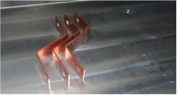
The connector is the visible part of a megawatt charging system. Inside the cabinet, current must also pass through converter outputs, protection devices, contactors, busbars, joints, and cable terminations. A generous connector rating does not prevent a poorly cooled internal connection from becoming the limiting component.
MCS development makes that distinction increasingly important. On 9 February 2026, CharIN announced the publication of IEC TS 63379, covering connectors, vehicle inlets, and cable assemblies for conductive DC charging at megawatt power levels. It is a Technical Specification for that interface scope, not a certification of every internal part of a complete charging station.
For busbar production planning, begin with the cabinet’s actual operating envelope and the interfaces it must serve. The copper samples pictured here illustrate formed terminal geometry; they are not identified as components from a certified MCS installation.
A Connector Standard Is Not a Cabinet Rating
Separate three layers in the project documentation: the vehicle connection interface, the charger power-conversion and distribution system, and the site’s electrical supply. Each has its own constraints and evidence.
CharIN’s MCS technology overview describes the wider charging-system development. For a purchase, however, obtain the exact connector, cable, charger, and vehicle-interface documentation proposed by the suppliers. Do not combine maximum values from different products into a rating that none of them actually supports.
The same caution applies to duty. A peak demonstration, a limited-duration operating point, and continuous operation under declared ambient conditions are different claims. Identify which one the cabinet design must support.
The existing EV charging infrastructure article addresses the broader application. This guide focuses on the internal conductor path rather than market-size estimates or connector dimensions.
Translate the Duty Cycle Into a Voltage-Current Envelope
Power alone does not size the current path. For a simplified DC calculation, I = P / V. At an assumed output of 1 MW, the current is 1,000 A at 1,000 V but 1,250 A at 800 V.
Those are illustrative operating points, not a statement that every charger supplies 1 MW at both voltages. The actual system may limit current and therefore reduce power at lower voltage. Obtain its permitted operating envelope, including charging duration, ambient conditions, and cooling limits.
Define the relevant load sequence. Repeated sessions with short recovery periods can create a different thermal condition from a single run starting with a cold cabinet. Include the expected sequence of power changes rather than treating the nameplate current as the entire duty cycle.
Also identify how modules share current. If parallel converter outputs feed a common bus, the branch conductors and common path need their own assessments. A total cabinet current does not establish equal branch current under every operating or fault condition.
The busbar drawing should be based on the approved electrical and thermal design. Increasing copper cross-section without checking enclosure conditions, joints, and terminal limitations may not remove the actual bottleneck.
Follow the Heat Through Each Terminal
For a connection represented by resistance R, the local resistive loss is P = I²R. Assume a 10 μΩ connection solely to illustrate sensitivity:
| Assumed current | Calculated loss at 10 μΩ |
|---|---|
| 1,000 A | 10 W |
| 1,250 A | 15.625 W |
| 1,500 A | 22.5 W |
The resistance in this example is not an acceptance threshold. Actual joints need an approved design and test method. The table shows why a modest increase in current can make thermal performance much more demanding.
Map where the heat goes. A liquid-cooled cable may control temperature along the cable while an internal busbar joint remains dependent on conduction and cabinet airflow. A cooled component can also introduce nearby condensation or leakage considerations that the assembly design must address.
For each connection, identify its permitted temperature, contact system, mounting conditions, and thermal path. Evaluate the assembled arrangement with covers, barriers, and cable routing in place. An open-door demonstration does not reproduce a closed cabinet’s airflow.
Use the busbar contact-resistance guide for joint design and measurement principles. Do not use a single micro-ohm reading to predict long-term thermal performance without considering the complete duty and joint condition.
Separate the Grid-Side Assembly From the DC Output Path
An MCS installation can include a grid connection, transformer, AC distribution, converter modules, and the DC output system. Their fault duties and protection requirements are not interchangeable.
The responsible electrical designer should identify fault sources and protective behavior at each stage, including stored energy where applicable. Protection devices need the appropriate voltage, current, interruption, and coordination characteristics for the circuit in which they operate.
The workshop needs the approved conductor arrangement and support requirements that follow from that assessment. It should not assume that an AC switchboard’s rating automatically covers a DC output assembly with a different source and protection system.
Maintenance isolation also belongs in the cabinet design. Service access should not require disturbing unrelated high-current joints every time a replaceable component is removed. The equipment manufacturer must define safe isolation and discharge procedures; fabrication convenience should support those procedures, not compromise them.
Design Interfaces for Movement and Repeatable Fabrication
Terminal alignment, thermal movement, and component replacement can influence geometry as much as the nominal current. Agree an interface drawing with each component supplier before releasing a formed bar.
The interface should state hole positions, contact lands, permitted loads, fastening requirements, insulation boundaries, and tolerances. Where movement is expected, establish its direction and magnitude using a thermal-expansion and support assessment. Do not make a rigid connection absorb installation error by force.
For fabrication, protect the electrical surfaces through punching, bending, finishing, cleaning, and handling. Keep each material and drawing revision traceable to the resulting part. If the geometry includes a short return or offset near a terminal, inspect the finished three-dimensional position rather than only the flat blank.
A DHAC-BB-H bending workstation can be evaluated for relevant rigid-bar geometries within its agreed capabilities. That does not establish the performance of flexible links, laminated stacks, welds, cooling components, or the complete charger. Define those processes separately in the EV and new-energy manufacturing scope.
Validate the Cabinet as a System
The component qualification plan should feed into a system test plan owned by the charger manufacturer. Include representative operating points and thermal cycles, the intended enclosure configuration, cooling behavior, and applicable abnormal-condition and protection evaluations.
Agree how temperature and electrical measurements will be taken so results can be compared between builds. Record the component versions, busbar drawings, joint assembly controls, and cooling configuration that belong to each test. A later layout change may invalidate an otherwise useful result.
Manufacturing acceptance should then confirm that production reproduces the tested arrangement. Check critical terminal positions, material identity, surface condition, support locations, and assembly records. Resolve deviations through engineering rather than treating them as cosmetic.
The procurement opportunity is not simply “more copper for megawatt charging.” It is a demand for controlled, verifiable current paths. A successful busbar package makes the cabinet easier to assemble, cool, inspect, and reproduce while staying within the system designer’s validated limits.
Frequently Asked Questions (FAQs)
Does every MCS installation deliver 3.75 MW?
No. An interface capability or headline maximum does not establish the delivered power of every charger. Actual operation depends on the charger's voltage-current envelope, vehicle request, cable and connector limits, cooling, and site capacity.
Does a liquid-cooled charging cable remove the need to evaluate cabinet joints?
No. The cable's cooling circuit does not automatically cool every internal busbar, joint, fuse, or contactor. Evaluate the thermal path and limits of each component in the assembled cabinet.
Must the entire DC output path use laminated busbars?
No. The appropriate construction depends on circuit inductance, geometry, current, insulation, movement, and manufacturing requirements. A low-inductance converter connection and a longer output distribution path can need different solutions.
Can precision busbar fabrication establish MCS charger compliance?
No. Fabrication can provide conforming components and traceable inspection evidence. System-level safety, communication, thermal performance, protection, and applicable conformity assessments remain the charger manufacturer's responsibility.
DHAC-BB-H Servo-Hydraulic Busbar Bender
Discover details, parameters, standard dies packages, and factory quotes.