
Hydraulic vs. Servo-Hydraulic Busbar Machines: Compare the Complete Duty Cycle
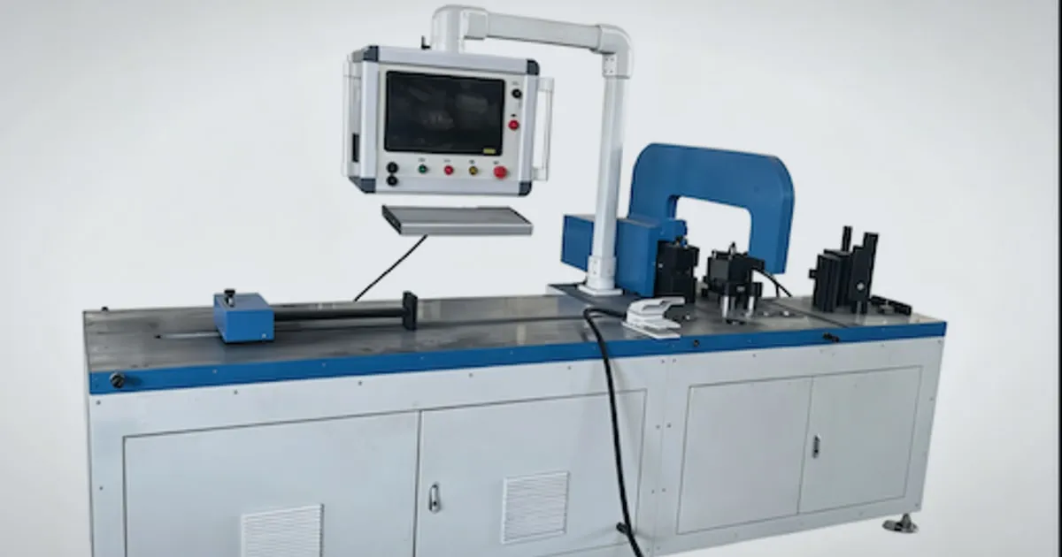
A servo-hydraulic label does not tell a busbar manufacturer how much electricity a machine will use or how accurately it will bend a part. The useful comparison is between complete systems running the same parts, with the same acceptance limits and a realistic mix of processing, handling and waiting time.
This guide separates pump-drive architecture from finished-part performance. DH CNC supplies busbar processing equipment; the comparison below is a purchasing and test framework, not an independent benchmark or a claim that every servo-equipped machine outperforms every conventional hydraulic machine.
Identify the hydraulic architecture first
Conventional hydraulics are not a single design. A fixed-speed motor can drive a fixed-displacement pump with unloading control or a variable-displacement pump that adjusts its delivery. Those circuits do not have identical idle losses. A variable-speed pump drive adds another way to match flow to demand.
| Architecture | How demand is managed | What to establish in the quotation |
|---|---|---|
| Fixed-speed, fixed-displacement pump | Valves route, regulate or unload the pump flow | Pressure and power during idle, approach, working stroke and return |
| Fixed-speed, variable-displacement pump | Pump displacement changes with the circuit demand | Control mode, low-flow losses and response under the actual load |
| Variable-speed or servo pump drive | Motor speed and, where applicable, torque or pump displacement are controlled | Motor, drive, pump, feedback sensors and sleep/wake behavior |
Parker’s Drive Controlled Pump documentation explains demand-based pump control. Variable-speed operation is not limited to permanent-magnet servo motors; the motor and control package must be identified explicitly.
A servo-driven backgauge is not proof that the main hydraulic pump is servo-controlled. On a multi-station machine, ask which station has which drive and whether simultaneous operation changes the available pressure, flow or response.
Measure energy across the production cycle
The largest saving opportunity may occur between strokes, not during the highest-force operation. Bosch Rexroth’s Sytronix overview ties savings to the work cycle. Its product-level claims are not measured results for a DH CNC machine.
For a comparison, include:
- startup and warm-up;
- loading, alignment and program selection;
- approach, processing, pressure holding where required, and return;
- inspection, unloading and waiting between batches;
- cooling, control electronics and other machine auxiliaries;
- rejected parts and rework within the measurement boundary.
Record total electrical energy in kWh and accepted output. Report kWh per accepted part or per defined batch, together with the part mix and cycle time. A motor nameplate rating in kW is not a shift-energy measurement. A stopped pump does not mean the complete machine draws zero power.
For a clearly hypothetical example, assume two machines deliver the same accepted output over 2,000 operating hours per year. If their measured average whole-machine power is 3.0 kW and 1.8 kW, the difference is:
(3.0 − 1.8) kW × 2,000 h/year = 2,400 kWh/year
At an assumed electricity price of USD 0.15/kWh, that is USD 360/year in energy savings. A USD 3,600 installed-price premium would therefore take 10 years to recover from electricity alone, before financing or discounting. These are calculation inputs, not equipment prices, tariffs or promised savings. Include additional benefits only when they have been measured without double counting.
Separate position feedback from bend quality
An encoder can report motor or cylinder position; it does not necessarily measure the finished busbar angle after unloading. Repeatable motion helps process control, but the part still responds to grade, temper, thickness, grain direction, tool radius, friction and springback.
For each representative bend family, define:
- the material and tooling combination;
- the target angle and position tolerance on the unloaded part;
- the measurement datum, instrument and time after bending;
- the compensation recipe and permitted adjustments;
- the sample quantity and conditions from cold start to normal operating temperature.
The DHAC-BB-H product page lists published machine specifications. Convert those into agreed acceptance criteria for the buyer’s parts rather than treating an axis-resolution figure as a finished-part guarantee. The springback guide covers the associated material and setup considerations.
Check heat, noise and maintenance without fixed promises
Reducing avoidable hydraulic losses can reduce heat generation, but cooling requirements still depend on ambient temperature, workload, reservoir design and the complete circuit. Request oil-temperature records for the intended shift. Do not assume every servo system stays below a fixed temperature or can omit a cooler.
Noise comparisons need the same operating stage, measuring position and background conditions. A quiet idle phase does not establish the sound level during punching, shearing or a loaded bending stroke.
Oil-change intervals must follow the machine and fluid requirements, supported by operating conditions and oil-condition checks. Drive type alone cannot justify a universal extension from 2,000 to 5,000 hours. Include filters, seals, cooling equipment, drive diagnostics and replacement-part availability in the service comparison.
Request comparable technical evidence
| Purchase question | Evidence to request | Decision use |
|---|---|---|
| Is energy consumption lower? | Whole-machine kWh, accepted quantity and cycle breakdown for matched parts | Calculate savings with the plant’s operating hours and electricity rate |
| Is bend quality stable? | Individual measurements, material lot, tools, recipes and warm-up conditions | Check the drawing limits and variation across the batch |
| Is cooling adequate? | Oil and ambient temperatures over the specified workload | Confirm the supplied cooling scope |
| Is noise acceptable? | Measurement method, location and operating state | Compare like-for-like readings against project requirements |
| Can the plant maintain it? | Component list, backups, fault diagnostics, training and service terms | Assess downtime exposure and lifecycle cost |
For the DH303-8P three-station machine, include parallel-station operation in the test if the production plan depends on it. Independent hydraulic circuits and servo control are separate characteristics; neither should be inferred from the other.
Put the comparison into FAT
- Freeze the test drawings, material lots, tooling and acceptance limits.
- Define the measurement boundary, warm-up, batch size and realistic handling intervals.
- Run the agreed part mix and record energy, elapsed time and accepted output together.
- Measure critical dimensions, including bend angle after unloading, and log any adjustment or rework.
- Check temperature, noise, fault recovery and simultaneous operation where applicable.
- Keep raw readings, program revisions, deviations and the agreed corrective actions with the FAT record.
Use the busbar machine FAT/SAT protocol to integrate these checks with the wider equipment acceptance plan. An energy comparison does not replace machine safety or electrical verification.
Choose the drive within the complete production layout
A well-sized conventional hydraulic system may fit a modest or steady workload and an established maintenance team. A variable-speed or servo-hydraulic system deserves closer evaluation when demand varies substantially, idle periods are frequent or the proposed controls solve a demonstrated process problem.
Make the decision on accepted output, total installed scope and measured operating costs. Compare the drive only after deciding whether the factory needs a three-station workstation or separate punching, shearing and bending equipment in the machine selection guide. Faster pump response cannot resolve an unrelated loading, tooling or inspection bottleneck.
Frequently Asked Questions (FAQs)
Does a servo-hydraulic busbar machine use no electricity while idle?
No. The pump motor may slow down or stop when the circuit permits, but the controller, drive electronics, fans and other auxiliaries can still consume electricity. Measure whole-machine standby power and energy per accepted part under the intended production cycle.
Does a servo drive guarantee the finished bend angle?
No. Motor control and cylinder-position feedback are different from measuring the unloaded part angle. Material temper, tooling, springback, setup and the measurement method still affect the result. Agree on a part-level acceptance test using the buyer's material and drawings.
When does a variable-speed hydraulic drive justify its additional cost?
It is worth evaluating when the production cycle includes substantial low-flow or idle periods, or when verified process-control improvements have economic value. Calculate the result from measured energy, accepted output, service costs and the quoted installed-price difference; there is no universal payback period.
DHAC-BB-H Servo-Hydraulic Busbar Bender
Discover details, parameters, standard dies packages, and factory quotes.