
Surface Treatments for Power Busbars: Electro-Tinning, Silver Plating, and Corrosion Protection
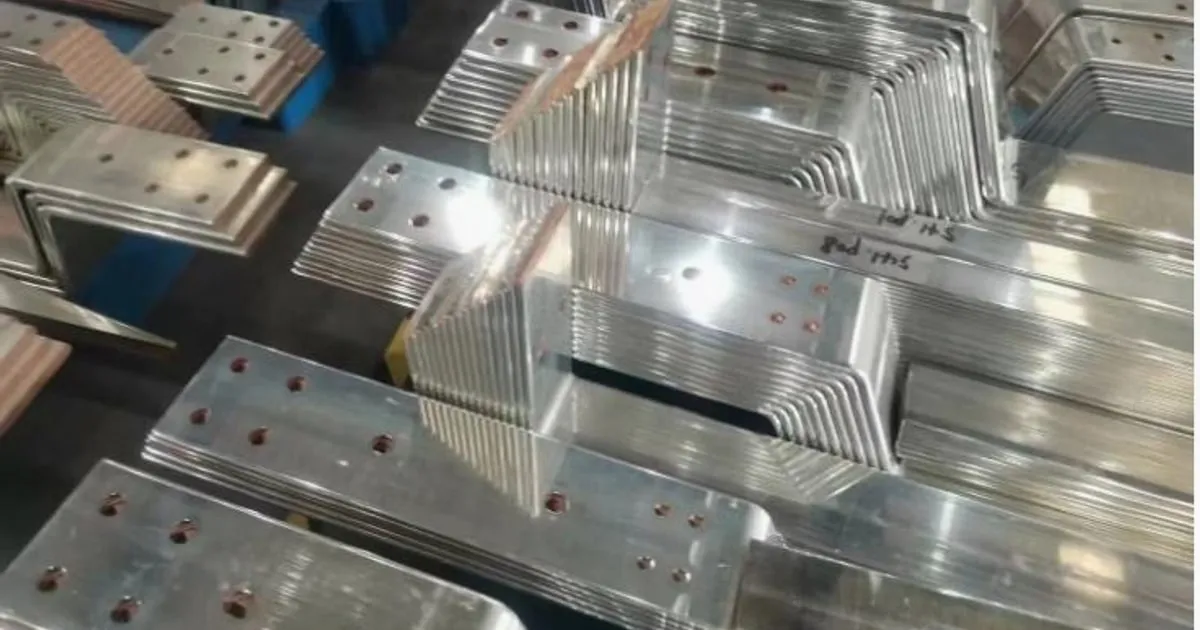
In heavy electrical power distribution, high-conductivity copper is the preferred material for carrying massive currents. However, bare copper is highly susceptible to atmospheric oxidation. Over time, exposure to oxygen, ambient humidity, and corrosive chemical agents (such as sulfur dioxide in industrial plants) reacts with the metal surface.
This reaction produces a thin, highly resistive film of copper oxide ($\text{CuO}$ or $\text{Cu}_2\text{O}$). In high-power switchboards, transformers, and industrial busduct systems, increased contact resistance at bolted connection points leads to severe localized heating, energy losses, and eventual joint failure.
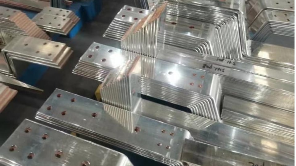
To maintain low joint contact resistances and guarantee compliance under international standards (such as IEC 61439-1), bare busbars undergo chemical surface treatments. This paper compares the primary B2B industrial plating protocols: Electro-Tinning, Silver Plating, and Nickel Plating.
1. The Chemistry of Joint Contact Resistance
The overall electrical resistance of a bolted busbar joint ($R_{\text{joint}}$) is divided into two factors:
$$R_{\text{joint}} = R_{\text{bulk}} + R_{\text{contact}}$$
Where:
- $R_{\text{bulk}}$ = The structural resistance of the copper material itself.
- $R_{\text{contact}}$ = The contact interface resistance, which is heavily dictated by surface plating and micro-asperities (microscopic high points where the metal physically touches).
When bare copper oxidizes, its contact resistance raises exponentially. Plating the surface with a highly stable, oxidation-resistant metal ensures that even when joints are tightened under standard torque profiles, the contact resistance remains low and stable over decades of service.
2. Industrial Plating Methods Compared
A. Electro-Tinning (The B2B Standard)
Electro-tinning is the most widely specified surface treatment for industrial low-voltage switchboards and power distribution systems.
- The Process: Copper bars are submerged in an acidic or alkaline bath, where an electric current deposits a uniform, continuous layer of pure tin ($\text{Sn}$).
- Thickness Standard: For typical B2B switchgear cabinets, a thickness of $8 \text{ to } 12 \text{ microns}$ ($\mu\text{m}$) is specified under ISO 2093.
- Performance Characteristics: Tin is relatively soft. When joint bolts are torqued, the soft tin layer deforms plastically, filling micro-asperities and creating a highly air-tight contact zone with minimal resistance. It offers excellent cost-efficiency and reliable corrosion protection up to operating temperatures of $100^\circ\text{C}$.
B. Silver Plating (Premium High-Power Standard)
Silver ($\text{Ag}$) features the highest electrical and thermal conductivity of all metals, making it the premier choice for high-voltage (HV) substations, generator terminal joints, and heavy-current busducts.
- Thickness Standard: Typically $3 \text{ to } 5 \text{ microns}$ ($\mu\text{m}$) is sufficient due to silver’s exceptional performance.
- Performance Characteristics: Unlike tin, silver maintains its electrical integrity even when slight surface oxidation occurs. Silver oxide ($\text{Ag}_2\text{O}$) remains semi-conductive, preventing the rapid thermal runaway common in oxidized tin or copper joints. Furthermore, silver plating remains highly stable at elevated operating temperatures exceeding $150^\circ\text{C}$.
- The Drawback: High raw material acquisition costs, and susceptibility to tarnishing (forming silver sulfide) when exposed to sulfur-rich atmospheres.
C. Nickel Plating (Extreme Environment Protection)
Nickel ($\text{Ni}$) plating is utilized in specialized industrial settings characterized by highly corrosive atmospheres, such as chemical processing plants, marine platforms, and high-sulfur paper mills.
- Performance Characteristics: Nickel exhibits exceptional hardness and chemical resistance. However, because its conductivity is lower than tin or silver, it yields a higher initial contact resistance. It is often utilized as a barrier diffusion layer underneath silver plating to prevent copper-silver migration at high temperatures.
3. Plating Sourcing Selection Matrix
| Plating Profile | Thickness Standard | Operating Temp Limit | Contact Resistance | Corrosion Resistance | Primary Applications |
|---|---|---|---|---|---|
| Bare Copper | None | $85^\circ\text{C}$ (IEC limit) | High (due to oxide) | Low | Low-load, indoor, dry enclosures |
| Electro-Tinning | 8 - 12 µm | $105^\circ\text{C}$ | Low | High | LV/MV Switchgear, Panel boards, Sourcing baseline |
| Silver Plating | 3 - 5 µm | $150^\circ\text{C}+$ | Ultra-Low | High (tarnishes) | HV Substations, Generator busducts, Transformers |
| Nickel Plating | 5 - 10 µm | $200^\circ\text{C}+$ | Moderate | Extreme | Marine, high-sulfur chemical plants |
4. The Sourcing Flow: Machining Before Plating
A common mistake in electrical cabinet fabrication is utilizing pre-plated copper stock sheets and executing punching and shearing operations afterward.
This introduces severe technical defects:
- Exposed Cut Margins: Shearing or punching pre-plated copper sheets exposes raw, unplated copper along the entire cut boundary. This raw edge oxidizes rapidly, and in damp environments, initiates galvanic corrosion along the plating interface.
- Tooling Wear and Delamination: The mechanical force of high-speed coordinates punching on a turret press can cause the plating layer to peel or delaminate around the hole edges.
The Correct Engineering Workflow:
Raw T2 Copper Bar ➔ [ High-Precision CNC Punch & Shear ] ➔ [ Bending and Forming ] ➔ [ Acid Cleaning Bath ] ➔ [ Electro-Chemical Plating ]To execute this workflow successfully without dimensional deviation, manufacturers rely on an integrated CNC punching and shearing center or a versatile 3-in-1 multi-station busbar processor. These systems punch coordinates and shear bars down to precise tolerances of ±0.15mm, ensuring that when finished parts are sent to chemical plating lines, they fit together with absolute accuracy during final switchboard assembly.
Manufacturers are invited to request a custom engineering layout consultation to review their component designs and establish grid-compliant tooling layouts prior to equipment procurement.
Frequently Asked Questions (FAQs)
Why must bare copper busbars be plated in electrical switchboards?
Bare copper oxidizes when exposed to oxygen and humidity, forming a non-conductive copper oxide layer (CuO). This layer increases electrical contact resistance at bolted joints, generating extreme heat and raising flashover arc risks.
Should you punch and shear busbars before or after chemical plating?
Always punch, shear, and bend busbars first, then perform chemical plating. Machining pre-plated bars exposes raw, unplated copper on the cut edges, creating rapid oxidation boundaries and galvanic corrosion cells.
DHCNC-BP-60 CNC Punching & Shearing Workstation
Discover details, parameters, standard dies packages, and factory quotes.